
User Manual


UnDerstanDIng the “Feel” oF Inventor
|
11
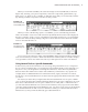
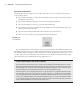
When you work with assemblies, the active tab changes to the Assemble tab (as shown in
Figure 1.10), allowing you to place components, create new components, pattern them, copy
them, and so on. There are also a number of other tabs shown that you can manually switch to
(by clicking on them) at any time to use the tools they contain.
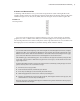
When you create a 2D drawing of parts or assemblies, you are automatically presented
with tools needed to create views and annotation. By default, the Place Views tab is displayed
because you need to create a view of a model before annotating it. However, you can manually
switch to the Annotate tab by clicking it. Figure 1.11 shows the active Place Views tab and the
inactive Annotate tab next to it.
As you can see, the collection of tabs (called the Ribbon menu) changes intuitively with every
task or environment you switch to. With a task-based user interface, there is no need to display
every possible tool all at once. In the next section you will explore more of the user interface.
Using General Tools vs. Specific Commands
In this section you’ll see how Inventor tools are set up, using AutoCAD tools as a comparison.
If you’ve never used AutoCAD, you can still gain some insight from this section, although you
may have to use your imagination concerning the references to AutoCAD. A key difference
between AutoCAD and Inventor is that in AutoCAD many commands are very specific. For
example, there are different dimension commands for lines, angles, and circles. In contrast,
Inventor has one General Dimension tool that creates the appropriate dimension based on what
you select.
For instance, in AutoCAD you might select the horizontal dimension tool to place a dimen-
sion on a horizontal line, then select the diameter dimension tool to place a dimension on a hole,
then select a radius dimension tool to place a dimension on a fillet, and so on. But in Inventor
you select the General Dimension tool, select a horizontal line, and you get a horizontal dimen-
sion; then, without exiting the General Dimension tool, you select a circle, and you automatically
get a diameter dimension. And of course to dimension a fillet, you continue with the General
Dimension tool, and you will automatically get a radius dimension.
Figure 1.10
The Assemble tab
and assembly tools
Figure 1.11
The drawing tabs
and drawing tools
016824c01.indd 11 4/29/11 6:56:15 AM