
User Manual


10
|
CHAPTER 1 Inventor DesIgn PhIlosoPhy
to constrain to in the assembly and it will be much more stable. However, if you constrain the
parts by selecting model features, you run the risk of constraints failing once a revision to a part
changes or removes the originally referenced geometry. To build a completely “bulletproof”
assembly, you could constrain the origin geometry of each part to the origin geometry of the
assembly. In this way, no matter how the geometry of the parts changes, it will not cause issues
with assembly constraints.
You will learn more about how to create assemblies, set up search paths to avoid manual
file resolutions, and work with grounded components in the coming chapters, but you should
remember these concepts and work to abide by them.
Understanding the “Feel” of Inventor
To the new user, Inventor’s ever-changing interface may seem a bit disorienting. Taking a few
minutes to understand why menus and tools change from one context to another will go a long
way in getting comfortable with the “feel” of Inventor and anticipating the way it works.
Understanding the Intuitive Interface
The overall interface of Inventor might be called context intuitive, meaning that menus change
depending on the task and the environment. Inventor is organized by tools grouped onto tabs,
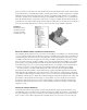
offering only the tools needed for the appropriate task at hand. If you are sketching a base fea-
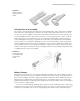
ture, the tools you see are sketch tools. In Figure 1.8, the Sketch tab is active, and the displayed
tools are the ones used to create and dimension sketches.
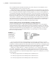
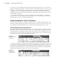
Upon the completion of a sketch, click the Finish Sketch button on the far right, and you will
exit the sketch. The Model tab then becomes active and the Sketch tab is hidden. This allows you
to see the tools that are appropriate for the immediate task, and only those tools, without hav-
ing to hunt around for them. If you create a new sketch or edit an existing one, the Sketch tab is
immediately brought back. Figure 1.9 shows the active Model tab.
Figure 1.8
The Sketch tab and
sketch tools
Figure 1.9
The Model tab
and model tools
016824c01.indd 10 4/29/11 6:56:14 AM