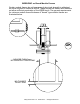
Washer, Electrical Equipment Bond WEEB Patent Pending INSTALLATION INSTRUCTIONS For Professional Solar only Please read carefully before installing. WEEB-PMC WEEBL-6.7 assembly WEEB Bonding Jumper - 6.7 Products are tested to UL 467 UL standard for safety grounding and bonding equipment Document Number 104-0404-000008-010 Wiley Electronics LLC.
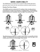
WEEB COMPATIBILITY The WEEB family of products can be used to bond anodized aluminum, galvanized steel, steel and other electrically conductive metal structures. Standard Top Down Clamps The WEEBs used for bonding the PV modules to the mounting rails are compatible with various cross-sections of module frames. The following are examples of module frames that are compatible. Notice that the WEEB teeth are positioned completely under the edge of the module frame.
Top Down Clamps for Lipped Modules The following are a few variations of lipped solar modules mounted with inverted U-shaped clamps. Notice that the force which the inverted Ushaped clamp exerts is in line with the WEEB teeth. OK Low-Lipped Module The WEEB-PMC is not compatible with high lipped modules. The WEEB teeth do not intersect with the solar module frame. X High-Lipped Module Wiley Electronics LLC.
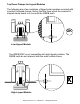
WEEB COMPATIBILITY Module frames like those shown here may have a ridge or lip on the bottom edge of the frame that would prevent the WEEB teeth from fully embedding. X Shown here is an example of a groove that will prevent the WEEB teeth from properly penetrating the module frame. This type of frame is not compatible with the WEEB. X Shown here is an example of a lip that will prevent the WEEB teeth from properly penetrating the module frame. This type of frame is not compatible with the WEEB.
WEEB-PMC on Boxed Module Frames Certain module frames do not have enough structural strength to withstand the force required to embed a WEEB. These frames will deform and therefore not allow sufficient penetration of the WEEB teeth. The general requirements for minimum module frame thickness of "boxed" type module frames are illustrated below. OK NO LESS THAN 3mm NO GREATER THAN 8.5MM NO THINNER THAN 1.5mm Wiley Electronics LLC.
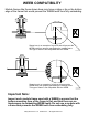
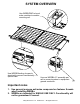
SYSTEM OVERVIEW Use WEEB-PMC to bond solar modules to module mounting rail. Use WEEB Bonding Jumper to electrically connect mechanically spliced rails. Use one WEEBL-6.7 assembly per rail to connect system to equipment ground conductor. Important notes 1. Use general purpose anti-seize compound on fastener threads when installing WEEBs. 2. WEEBs are intended for SINGLE USE ONLY. Functionality will not be guaranteed if reused. Wiley Electronics LLC.
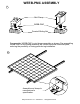
1 WEEB-PMC ASSEMBLY Mid Clamp WEEB-PMC Dovetail Sliding Nut Pre-assemble WEEB-PMC to mid-clamp assembly as shown. Pre-assembling WEEB-PMC to mid-clamp assembly will contain the small individual parts, reducing the possibility of losing parts during installation. 2 Assemble end clamp to manufacturer's specification. Wiley Electronics LLC.
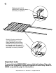
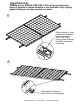
3 Slide pre-assembled WEEB-PMC and mid-clamp assembly into position. Slightly lift solar module and slide WEEB-PMC and midclamp assembly into position. WEEB teeth will automatically be aligned under the edge of the module when the mid-clamp assembly is correctly installed. Important note: To correctly install WEEB-PMC, ensure that both sides of the solar modules are completely positioned against the mid-clamp. Refer to WEEB compatibility page for illustrations. Wiley Electronics LLC.
Important note: WEEBs are for SINGLE USE ONLY! Do not torque fasteners down if position of solar modules is not finalized. Only slightly tighten fasteners to keep modules in place. 4 When position of solar modules are finalized, torque fasteners to 15ft-lb / 20.5 N-m using general purpose anti-seize compound on threads. 5 Assemble end clamp to manufacturer's specification. Wiley Electronics LLC.
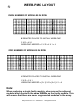
WEEB-PMC LAYOUT 6 EVEN NUMBER OF MODULES IN ROW x x x x X DENOTES PLACES TO INSTALL WEEB-PMC CXR=4X1 WEEB-PMC NEEDED = C X R = 4 X 1 = 4 ODD NUMBER OF MODULES IN ROW x x x x x x X DENOTES PLACES TO INSTALL WEEB-PMC CXR=5X1 WEEB-PMC NEEDED = [C+1] X R = [5+1] X 1 = 6 Note: When replacing a single faulty module, also remove the adjacent module which contacts the same WEEBs as the faulty module. This will ensure that there are never ungrounded modules in the array. Wiley Electronics LLC.
WEEBLUG ASSEMBLY 7 Drill bolt clearance hole 17/64in / 7mm on center of vertical rail support . For best aesthetics, drill hole on least visible side of rail. WEEB teeth towards rail Assemble WEEBL-6.7 assembly and torque fasteners to 10 ft-lb / 13.5 N-m using general purpose anti-seize compound on threads. Important note: WEEB-6.7 that sits under the WEEBLug is for SINGLE USE ONLY! Ensure position is correct before tightening. Wiley Electronics LLC.
8 Equipment ground conductor Lay in equipment ground conductor and torque bolt to 7 ft-lb / 10 N-m. Wiley Electronics LLC.
PMC SPLICE KIT ASSEMBLY 9 WEEB Bonding Jumper can be used for all rail splices including expansion joints. WEEB Bonding Jumper Pro-Solar mechanical splice Torque fasteners to 10 ft-lb / 13.5 N-m using general purpose anti-seize compound on threads. Wiley Electronics LLC.