Wiley Electronics LLC Washer, Electrical Equipment Bond WEEB Patent Pending INSTALLATION INSTRUCTIONS For DP&W Solar Power FAB™ CRS Only Please read carefully before installing. Wiley Electronics recommends that sufficient details of the installation be submitted to the AHJ for approval before any work is started. WEEB-DPF WEEB-11.5 WEEB-9.5 WEEBL-8.
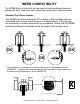
WEEB COMPATIBILITY The WEEB family of products can be used to bond anodized aluminum, galvanized steel, steel and other electrically conductive metal structures. Standard Top Down Clamps The WEEBs used for bonding the PV modules to the mounting rails are compatible with various cross-sections of module frames. The following are examples of module frames that are compatible. Notice that the WEEB teeth are positioned completely under the edge of the module frame.
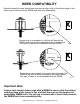
WEEB COMPATIBILITY Module frames like those shown here may have a ridge or lip on the bottom edge of the frame that would prevent the WEEB teeth from fully embedding. X Shown here is an example of a lip that will prevent the WEEB teeth from properly penetrating the module frame. This type of frame is not compatable with the WEEB X Shown here is an example of a groove that will prevent the WEEB teeth from properly penetrating the module frame.
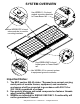
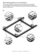
SYSTEM OVERVIEW Use WEEB-11.5 to bond module mounting brackets to Power Beam rail. Use WEEB-DPF to bond solar modules to module mounting brackets. Use WEEB-WMC to bond ballast pans to Power Beam rail. Use WEEBL-8.0 to connect system to equipment ground conductor. Important Notes: 1. The NEC section 690.43 states, "Exposed non-current carrying metal parts of module frames, equipment, and conductor enclosures shall be grounded in accordance with 250.134 or 250.136(A) regardless of voltage." 2.
Module Mounting Brackets and Joiner Brackets Use at least one WEEB-11.5 under every mounting bracket and joiner bracket. Use more than one when that bracket joins two or more separate rails together. Place one WEEB-11.5 on the T-bolt of each individual rail, under a module mounting bracket or joiner bracket. 1 Wiley Electronics LLC.
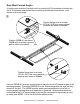
East-West Formed Angles If running wire outside of conduit and in or along the E-W members or ballast tray, the E-W members and ballast trays must be grounded as shown below, or as shown on the next page. 2 Tighten flange nuts to at least 15 ft-lb / 20.5 N-m using general purpose anti-seize on threads. Position WEEB-9.5 as shown. WEEB will not create a ground path in other orientations. Tighten flange nuts to at least 15 ft-lb / 20.5 N-m using general purpose anti-seize on threads. Use one WEEB-9.
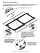
Ballast Pans and Rail Splices If running wire outside of conduit and in or along the ballast tray, the ballast trays may be connected to equipment ground by using one WEEB-WMC at one of the connection points. Use one WEEB-WMC per ballast pan to bond pans to Power Beam rail. 3 Use a WEEB-WMC at each splice plate mounting hole. Tighten each flange nut to at least 15 ft-lb / 20.5 N-m using general purpose anti-seize on threads.
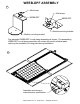
WEEB-DPF ASSEMBLY 4 Mid-clamp Mid-clamp WEEB-DPF WEEB-DPF Module mounting bracket Module mounting bracket Pre-assemble WEEB-DPF to mid-clamp assembly as shown. Pre-assembling WEEB-DPF to mid-clamp assembly will contain the small individual parts, reducing the possibility of losing parts during installation. 5 Assemble end clamp to manufacturer's specification. Wiley Electronics LLC.
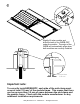
6 Slightly lift solar module and slide the teeth of the WEEB-DPF under the module. The edge of the WEEB will automatically align when both modules are correctly installed. No more than 3.00 mm Important note: To correctly install WEEB-DPF, each side of the mid-clamp must cover at least 135 mm² of the module frame. This means that there can be no more than 3.0 mm of space between the mid-clamp and the module frame. Check with the module manufacturer for any additional installation requirements.
Important note: 7 WEEBs are for SINGLE USE ONLY! Do not torque fasteners down if position of solar modules is not finalized. Only slightly tighten fasteners to keep modules in place. When position of solar modules is finalized, torque fasteners to 15 ft-lb / 20.5 N-m using general purpose anti-seize on threads. 8 Assemble end clamp to manufacturer's specification. Wiley Electronics LLC.
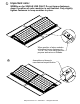
WEEB-DPF LAYOUT EVEN NUMBER OF MODULES IN ROW x x x x X DENOTES PLACES TO INSTALL WEEB-DPF C = Column R = Row CXR=4X1 WEEB-DPF NEEDED = C X R = 4 X 1 = 4 ODD NUMBER OF MODULES IN ROW x x x x x x X DENOTES PLACES TO INSTALL WEEB-DPF CXR=5X1 WEEB-DPF NEEDED = [C+1] X R = [5+1] X 1 = 6 Important Note: When replacing a single faulty module, also remove the adjacent module which contacts the same WEEBs as the faulty module. This will ensure that there are never ungrounded modules in the array.
WEEB QUANTITIES WEEB WEEB-DPF WEEB-9.5 WEEB-11.5 WEEB-WMC QUANTITY NEEDED • • See calculations on previous page 2 for every E-W Formed Aluminum Angle • At least 1 under every module tilt bracket (1 for every rail joined to the bracket) • 1 at every hole of every tie plate • 1 for every Ballast Pan connected to an E-W Formed Aluminum Angle • 2 for every 2-Hole Side Splice • 1 for every Ballast Pan connected to a Power Beam Extrusion Wiley Electronics LLC.
9 WEEBLUG ASSEMBLY Assemble WEEBL-8.0 using the DP&W T-bolt and Flange nut. Torque flange nut to 10 ft-lb / 13.5 N-m using general purpose anti-seize on threads. Important Notes: The WEEB-8.0 that sits under the lug is for SINGLE USE ONLY! Ensure position is correct before tightening. WEEBL-8.0 may be used with a maximum equipment ground wire of 6 AWG. Wiley Electronics LLC.
10 Lay in equipment ground conductor and torque bolt to 7 ft-lb / 10 N-m using general purpose anti-seize on threads. Equipment ground conductor Wiley Electronics LLC.