SFF8639 Test Adapter User Manual (Preliminary) SFF‐8639 Test Adapter User Manual P a g e |1 ©2014 Wilder Technologies, LLC Document No. 910‐0034‐000 Rev.
SFF8639 Test Adapter User Manual (Preliminary) Table of Contents Introduction ..................................................................................................................................... 3 Product Inspection .......................................................................................................................... 5 The SFF‐8639 Test Adapter Care and Handling Precautions ...........................................................
SFF8639 Test Adapter User Manual (Preliminary) Introduction This user’s manual documents the SFF‐8639 Plug and Receptacle Test Adapters (8639‐TPA‐P and 8639‐TPA‐R). The two test adapter types, shown in Figures 1 and 2, test 8639 interface cables, hosts and devices against the SFF‐8639 Specification. NOTE: The test adapters referred to and illustrated in this “General” section of the User Manual, reflect the “Universal” SFF‐ 8639 Test Adapters.
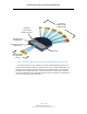
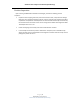
SFF8639 Test Adapter User Manual (Preliminary) 22 Female SMAs for High‐ Speed Testing 4‐Position +5V and +12V Power Connector 8639 Receptacle (68‐Position) Low‐Speed Connector (16‐position) Housing 6 Female SMAs for High‐Speed Testing Figure 2. The 8639 Test Adapter (Device Receptacle). Universal SFF-8639 Device Test Fixture Shown. The 4‐position power connector is Molex part number 53109‐0410 (Mating connector not provided). The 16‐position keyed/latching mating connector part number is 43045‐1602.
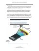
SFF8639 Test Adapter User Manual (Preliminary) Product Inspection Upon receiving the 8639‐TPA from Wilder Technologies, perform the following product inspection: Inspect the outer shipping container, foam‐lined instrument case, and product for damage. Retain the outer cardboard shipping container until the contents of the shipment have been inspected for completeness and the product has been checked mechanically and electrically.
SFF8639 Test Adapter User Manual (Preliminary) The SFF‐8639 Test Adapter Care and Handling Precautions The SFF‐8639 Test Adapter requires careful handling to avoid damage. Improper handling techniques, or using too small a cable bend radius, can damage the coaxial cable connections within the adapter housing or the cables themselves. This can occur at any point along the cable.
SFF8639 Test Adapter User Manual (Preliminary) 3. The 8639‐TPA SMA connectors have flats that accept an open‐end 1/4‐inch or 6.5mm wrench. When attaching instrument cables to the 8639‐TPA, it is recom‐ mended that the 8639‐TPA SMA connectors be mechanically held and the test leads be tightened to the equipment manufacturer’s torque recommendations, normally 5 in‐lbs, using a 5/16‐inch open‐end wrench.
SFF8639 Test Adapter User Manual (Preliminary) General Test Adapter, Cable, and Connector Observing simple precautions can ensure accurate and reliable measurements. Handling and Storage Before each use of the 8639‐TPA, ensure that all connectors are clean. Handle all cables carefully and store the 8639‐TPA in the foam‐lined instrument case when not in use, if possible. Do not set connectors contact end down. Install the SMA protective end caps when the 8639‐TPA is not in use.
SFF8639 Test Adapter User Manual (Preliminary) Electrostatic Discharge Information Protection against electrostatic discharge (ESD) is essential while connecting, inspecting, or cleaning the 8639‐TPA test adapter and connectors attached to a static‐sensitive circuit (such as those found in test sets). Electrostatic discharge can damage or destroy electronic components.
SFF8639 Test Adapter User Manual (Preliminary) User Model The 8639‐TPA supports all testing of SFF‐8639 related interface specifications such as PCIe SFF‐8639, SATA Express, MultiLink SAS, and others. It is capable of performing beyond the scope of measurements required, limited only by the specifications, environmental, care and handling as stated in this document. The following examples are suggestions for possible testing setups.
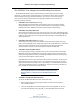
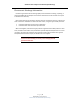
SFF8639 Test Adapter User Manual (Preliminary) The third example shows one 8639 Plug TPA and one 8639 Receptacle TPA used for testing a 8639 extension cable: Physical Links Under Test Mated Connectors 8639 Plug TPA SFF‐8639 Extension Cable Reference Transceiver 8639 Receptacle TPA Mated Connectors Physical Links Under Test P a g e | 11 ©2014 Wilder Technologies, LLC Document No. 910‐0034‐000 Rev.
SFF8639 Test Adapter User Manual (Preliminary) Calibration Through De‐Embedding The SFF‐8639 Host and Device Test Adapters are fully passive components. Therefore, calibration compensating for the losses must occur within the test instrumentation that drives the SFF‐8639 receiver or looks at the response of the SFF‐8639 transmitter. The 8639‐TPAs have Touchstone S4P files for de‐embedding the electrical length and losses within the TPA up to the SFF‐8639 connector interface pads.
SFF8639 Test Adapter User Manual (Preliminary) Mechanical and Environmental Specifications NOTE: All specifications in this manual are subject to change. Table 1. General Specifications ITEM DESCRIPTION Usage Environment Controlled indoor environment Plug Test Adapter Length (w/standard cables) 246 mm +/‐ 2 mm (9.70 inches +/‐ .08 inches) (Characteristic) Receptacle Test Adapter Length (w/std. cables) 381 mm +/‐ 2 mm (15.00 inches +/‐ .
SFF8639 Test Adapter User Manual (Preliminary) Table 2. 8639-TPA-R 4-Position Power Connector “J2” LABEL PIN NO. DESCRIPTION +12V Pin 1 +12 Volts GND Pin 2 Power Ground GND Pin 3 Power Ground +5V Pin 4 +5 Volts Table 3. 8639-TPA-R 16-Position Alternate Connector “J3” (“Universal” 8639-TPA-R Described) LABEL PIN NO.
SFF8639 Test Adapter User Manual (Preliminary) Table 4.
SFF8639 Test Adapter User Manual (Preliminary) Table 4.
SFF8639 Test Adapter User Manual (Preliminary) Table 4.
SFF8639 Test Adapter User Manual (Preliminary) 8639‐TPA‐P Cable Pin‐out The 8639‐TPA‐P cables provide 28 SMA connectors (access up to six lanes of PCIe differential TX and RX, and up to two differential reference clocks) and one 10‐Position low‐speed connector. Labels clearly mark each cable or connector. The following figure refers to the pin‐ description table for the plug connector.
SFF8639 Test Adapter User Manual (Preliminary) Table 5. 8639-TPA-P 10-Position Low-Speed Connector “J3” LABEL PIN NO.
SFF8639 Test Adapter User Manual (Preliminary) Table 6.
SFF8639 Test Adapter User Manual (Preliminary) Table 6.
SFF8639 Test Adapter User Manual (Preliminary) Table 6.
SFF8639 Test Adapter User Manual (Preliminary) 8639 Configuration Board When used with the 8639‐TPA‐P (Host Test Adapter), the 8639 Configuration Board provides access to IFDET# (P4) and PRSNT# (P10) signals. The use of the combined signals provides the ability to set and detect the appropriate device type (configuration). Jumper configurations are referenced and clearly marked on the board.
SFF8639 Test Adapter User Manual (Preliminary) Electrical Specifications NOTE: All specifications in this manual are subject to change. Table 7. Electrical Specifications SPECIFICATION MINIMUM TYPICAL MAXIMUM NOTES Differential Impedance (ohms), 70 ps Rise Time, 20 – 80 percent 94 106 All Differential Pairs, Receptacle and Plug, excluding 8639 connector.
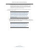
SFF8639 Test Adapter User Manual (Preliminary) Figure 7. Typical mated pair 6 Gb/s eye diagram, with de-embedding (top) and without de-embedding (bottom) P a g e | 25 ©2014 Wilder Technologies, LLC Document No. 910‐0034‐000 Rev.
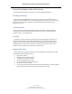
SFF8639 Test Adapter User Manual (Preliminary) Figure 8. Typical mated pair 6 Gb/s eye data, with de-embedding (top) and without de-embedding (bottom) P a g e | 26 ©2014 Wilder Technologies, LLC Document No. 910‐0034‐000 Rev.
SFF8639 Test Adapter User Manual (Preliminary) Figure 9. Typical mated pair 12 Gb/s eye diagram, with de-embedding (top) and without de-embedding (bottom) P a g e | 27 ©2014 Wilder Technologies, LLC Document No. 910‐0034‐000 Rev.
SFF8639 Test Adapter User Manual (Preliminary) Figure 10. Typical mated pair 12 Gb/s eye data, with de-embedding (top) and without de-embedding (bottom) P a g e | 28 ©2014 Wilder Technologies, LLC Document No. 910‐0034‐000 Rev.
SFF8639 Test Adapter User Manual (Preliminary) Figure 11. Typical mated pair balanced insertion loss, with de-embedding (top) and without de-embedding (bottom) P a g e | 29 ©2014 Wilder Technologies, LLC Document No. 910‐0034‐000 Rev.
SFF8639 Test Adapter User Manual (Preliminary) Figure 12. Typical mated pair balanced return loss, with de-embedding (top) and without de-embedding (bottom) P a g e | 30 ©2014 Wilder Technologies, LLC Document No. 910‐0034‐000 Rev.
SFF8639 Test Adapter User Manual (Preliminary) Figure 13. Typical TPA balanced return loss, differential termination replacing 8639 connector P a g e | 31 ©2014 Wilder Technologies, LLC Document No. 910‐0034‐000 Rev.
SFF8639 Test Adapter User Manual (Preliminary) Figure 14. Typical differential TDP of TPA-P connected to TPA-R at 100 ps Rise Time, All differential pairs. P a g e | 32 ©2014 Wilder Technologies, LLC Document No. 910‐0034‐000 Rev.
SFF8639 Test Adapter User Manual (Preliminary) Figure 15. Typical Differential NEXT, without connector (top) and with mated connectors (bottom), adjacent differential pairs, all differential pairs terminated at both ends. Into receptacle TPA shown. P a g e | 33 ©2014 Wilder Technologies, LLC Document No. 910‐0034‐000 Rev.
SFF8639 Test Adapter User Manual (Preliminary) 8639‐TPA Receptacle Accessories 8639‐TPA‐R Accessories The 8639‐TPA‐R (Device TPA) is supplied with Disk Support Adapter materials that allow the user to properly support and stabilize a 2.5 or 3.5‐inch form‐factor disk drive while under test. The figure, below, illustrates the installation and a typical application of the Disk Support Adapter materials. Disk Drive Under Test Thumb‐Screws and Disc Support Brackets Provided.
SFF8639 Test Adapter User Manual (Preliminary) Wilder Technologies, LLC – Limited Warranty Wilder Technologies, LLC warrants that each Test Adapter, 1) is free from defects in materials and workmanship and, 2) conforms to Wilder Technologies specifications for a period of 12 months. See Consumable and Fragile Material Warranty for exceptions to the 12 month warranty The warranty period for a Test Adapter is a specified, fixed period commencing on the date of ship from Wilder Technologies, LLC.
SFF8639 Test Adapter User Manual (Preliminary) Wilder Technologies, LLC – Terms & Conditions of Sale 1. Other Documents: This Agreement may NOT be altered, supplemented, or amended by the use of any other document(s) unless otherwise agreed to in a written agreement signed by both you and Wilder Technologies, LLC. If you do not receive an invoice or acknowledgement in the mail, via e‐mail, or with your Product, information about your purchase may be obtained at support@wilder‐tech.
SFF8639 Test Adapter User Manual (Preliminary) Compliance with Environmental Legislation Wilder Technologies, LLC, is dedicated to complying with the requirements of all applicable environmental legislation and regulations, including appropriate recycling and/or disposal of our products. WEEE Compliance Statement The European Union adopted Directive 2002/96/EC on Waste Electrical and Electronic Equipment (WEEE), with requirements that went into effect August 13, 2005.
SFF8639 Test Adapter User Manual (Preliminary) Glossary of Terms TERMINOLOGY DEFINITION Aggressor A signal imposed on a system (i.e., cable assembly) to measure response on other signal carriers. Decibel (dB) Ten times the common logarithm (i.e. log10) of the ratio of relative powers. Informative The designation of a test that is not required for compliance but is considered important from a characterization standpoint. It is provided for informational purposes only.
SFF8639 Test Adapter User Manual (Preliminary) Addendum A – Specific Configuration Test Adapters This addendum provides documentation of specific configuration (non‐Universal) SFF‐8639 test adapters (PCI Express, SATA Express, and SAS MultiLink) as to content and operation of each. PCI Express Specific Configuration Test Adapters This section contains illustrations of the 8639PE‐TPA‐P and 8639PE‐TPA‐R test adapters and the related 8639 Configuration Board used with the 8639PE‐TPA‐P test adapter.
SFF8639 Test Adapter User Manual (Preliminary) 8639PE‐TPA‐R Test Adapter Color ID for Differential Pair (See Table A‐2) Figure A‐2. 8639PE-TPA-R PCIe Specific Test Adapter P a g e | 40 ©2014 Wilder Technologies, LLC Document No. 910‐0034‐000 Rev.
SFF8639 Test Adapter User Manual (Preliminary) SATA Express Specific Configuration Test Adapters This section contains illustrations of the 8639SA‐TPA‐P and 8639SA‐TPA‐R test adapters and the related 8639 Configuration Board used with the 8639SA‐TPA‐P test adapter. USB Type A to Type B Cable (Provided with Universal TPA‐P and SATA Express TPA‐P). Required to Supply 1.
SFF8639 Test Adapter User Manual (Preliminary) Color ID for Differential Pair (See Table A‐2) 8639PE‐TPA‐R Test Adapter Figure A‐4. 8639SA-TPA-R SATA Express Specific Test Adapter P a g e | 42 ©2014 Wilder Technologies, LLC Document No. 910‐0034‐000 Rev.
SFF8639 Test Adapter User Manual (Preliminary) SAS MultiLink Specific Configuration Test Adapters This section contains illustrations of the 8639SX4‐TPA‐P and 8639SX4‐TPA‐R test adapters and the related 8639 Configuration Board used with the 8639SX4‐TPA‐P test adapter. Color ID for Differential Pair (See Table A‐1) 8639SX4‐TPA‐P Test Adapter 8639 Configuration Board Note Jumper Positions for SAS MultiLink Specific Configuration (JP2 Pin 1 to 2, JP3 Pin 2 to 3) Figure A‐5.
SFF8639 Test Adapter User Manual (Preliminary) 8639SX4‐TPA‐R Test Adapter Color ID for Differential Pair (See Table A‐2) Figure A‐6. 8639SX4-TPA-R SAS MultiLink Specific Test Adapter P a g e | 44 ©2014 Wilder Technologies, LLC Document No. 910‐0034‐000 Rev.
SFF8639 Test Adapter User Manual (Preliminary) Table A-1. TPA-P (8639 Specific Configuration Plug) Pin Assignments on keyed side of connector Connector Pin Number PCI Express 8639. Identification Marker, if Present (Name in Spec.) SATA Express. Identification Marker, if Present (Name in Spec.) SAS MultiLink. Identification Marker, if Present (Name in Spec.
SFF8639 Test Adapter User Manual (Preliminary) Table A-1. TPA-P (8639 Specific Configuration Plug) Pin Assignments on side opposed to keyed side of connector Pin Description Connector Pin Number PCI Express 8639. Identification Marker, if Present (Name in Spec.) SATA Express. Identification Marker, if Present (Name in Spec.) SAS MultiLink. Identification Marker, if Present (Name in Spec.
SFF8639 Test Adapter User Manual (Preliminary) Table A-1. TPA-P (8639 Specific Configuration Plug) Pin Assignments on side opposed to keyed side of connector (continued) Connector Pin Number PCI Express 8639. Identification Marker, if Present (Name in Spec.) SATA Express. Identification Marker, if Present (Name in Spec.) SAS MultiLink. Identification Marker, if Present (Name in Spec.
SFF8639 Test Adapter User Manual (Preliminary) Table A-2. TPA-R (8639 Specific Configuration Receptacle) Pin Assignments on keyed side of connector Connector Pin Number PCI Express 8639. Identification Marker, if Present (Name in Spec.) SATA Express. Identification Marker, if Present (Name in Spec.) SAS MultiLink. Identification Marker, if Present (Name in Spec.
SFF8639 Test Adapter User Manual (Preliminary) Table A-2. TPA-R (8639 Specific Configuration Receptacle) Pin Assignments on side opposed to keyed side of connector Pin Description Connector Pin Number PCI Express 8639. Identification Marker, if Present (Name in Spec.) SATA Express. Identification Marker, if Present (Name in Spec.) SAS MultiLink. Identification Marker, if Present (Name in Spec.
SFF8639 Test Adapter User Manual (Preliminary) Table A-2. TPA-R (8639 Specific Configuration Receptacle) Pin Assignments on side opposed to keyed side of connector (continued) Connector Pin Number PCI Express 8639. Identification Marker, if Present (Name in Spec.) SATA Express. Identification Marker, if Present (Name in Spec.) SAS MultiLink. Identification Marker, if Present (Name in Spec.
SFF8639 Test Adapter User Manual (Preliminary) Addendum B – 8639 Configuration Board Reference Information This addendum provides reference information for the 8639 Configuration Board with regard to the specific configuration (non‐Universal) SFF‐8639 test adapters (PCI Express, SATA Express, and SAS MultiLink). Additional details of the 8639 Configuration Board itself are also presented.
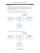
SFF8639 Test Adapter User Manual (Preliminary) 8639 Configuration Board Block Diagram 8639 low speed signals 1 GND GND 1 B Reset A Reset Wake# Device Reset Interface Detect# Present# TPA connector Mirrored connections of TPA Activity/Spin SMCLK SMDAT J3 1 JP1 SMCLK GND SMDAT 1 Wake# GND JP2 JP3 1 1 5k ohms to 1.8V Interface Detect# GND Present# GND Momentary Reset B Reset Momentary Reset A Reset Momentary Reset Power USB Regulator +3.
SFF8639 Test Adapter User Manual (Preliminary) Index +12V, 3 +3.3V, 3 +5V, 3 1.
Visit our website at www.wilder‐tech.com Wilder Technologies, LLC 6101A East 18th Street Vancouver, WA 98661 Phone: 360‐859‐3041 Fax: 360‐859‐3105 www.wilder‐tech.com ©2014 Wilder Technologies, LLC Document No. 910‐0034‐000 Rev.