SATA 2.5 Test Adapter User Manual SATA 2.5 Test Adapter User Manual P a g e |1 © 2010, 2011 Wilder Technologies, LLC Document No. 910‐0011‐000 Rev.
SATA 2.5 Test Adapter User Manual Table of Contents Introduction ..................................................................................................................................... 3 Product Inspection .......................................................................................................................... 5 The SATA 2.5 Test Adapter Care and Handling Precautions ........................................................... 6 General Test Adapter, Cable, and Connector .....
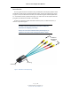
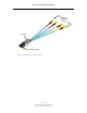
SATA 2.5 Test Adapter User Manual Introduction This user’s guide documents the SATA 2.5 Plug and Receptacle Test Adapters (SATA2.5‐TPA‐P and SATA2.5‐TPA‐R) and the associated Calibration Cables. The two test adapter types, shown in Figures 1 and 2, test SATA interface cables, hosts and devices against the SATA Specification 2.5. The Calibration Cables, presented on Page 15, are used to zero‐out test adapter attributes (using SOLT, with either the 1X‐THRU or the 2X‐THRU).
SATA 2.5 Test Adapter User Manual 4 SMAs for High‐Speed Testing Housing SATA Receptacle Figure 2. The SATA 2.5 Test Adapter (Receptacle) P a g e |4 © 2010, 2011 Wilder Technologies, LLC Document No. 910‐0011‐000 Rev.
SATA 2.5 Test Adapter User Manual Product Inspection Upon receiving the SATA2.5‐TPA from Wilder Technologies, perform the following product inspection: Inspect the outer shipping container, foam‐lined instrument case, and product for damage. Retain the outer cardboard shipping container until the contents of the shipment have been inspected for completeness and the product has been checked mechanically and electrically.
SATA 2.5 Test Adapter User Manual The SATA 2.5 Test Adapter Care and Handling Precautions The SATA 2.5 Test Adapter requires careful handling to avoid damage. Improper handling techniques, or using too small a cable bend radius, can damage the coaxial cable connections within the adapter housing or the cables themselves. This can occur at any point along the cable. To achieve optimum performance and to prolong the SATA2.
SATA 2.5 Test Adapter User Manual 3. The SATA2.5‐TPA SMA connectors have flats that accept an open‐end 1/4‐inch or 6.5mm wrench. When attaching instrument cables to the SATA2.5‐TPA, it is recom‐ mended that the SATA2.5‐TPA SMA connectors be mechanically held and the test leads be tightened to the equipment manufacturer’s torque recommendations, normally 5 in‐lbs, using a 5/16‐inch open‐end wrench.
SATA 2.5 Test Adapter User Manual General Test Adapter, Cable, and Connector Observing simple precautions can ensure accurate and reliable measurements. Handling and Storage Before each use of the SATA2.5‐TPA, ensure that all connectors are clean. Handle all cables carefully and store the SATA2.5‐TPA in the foam‐lined instrument case when not in use, if possible. Do not set connectors contact end down. Install the SMA protective end caps when the SATA2.5‐TPA is not in use.
SATA 2.5 Test Adapter User Manual Electrostatic Discharge Information Protection against electrostatic discharge (ESD) is essential while connecting, inspecting, or cleaning the SATA2.5‐TPA test adapter and connectors attached to a static‐sensitive circuit (such as those found in test sets). Electrostatic discharge can damage or destroy electronic components.
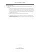
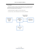
SATA 2.5 Test Adapter User Manual User Model The SATA2.5 TPA supports all testing of the SATA Specification 2.5. It is capable of performing well beyond the scope of measurements required, limited only by the specifications, environ‐ mental, care and handling as stated in this document. The following examples are suggestions for possible testing setups. In this first example, a SATA 2.5 Receptacle TPA is used to test a SATA device: Physical Links Under Test Laboratory Sourced Signal SATA 2.
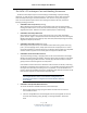
SATA 2.5 Test Adapter User Manual In the second example, the SATA 2.5 Plug TPA and a SATA internal cable assembly is used to test a SATA host: Laboratory Sourced Signal SATA Internal Cable SATA 2.5 Plug TPA SATA Host Under Test Physical Links Under Test Laboratory Load P a g e | 11 © 2010, 2011 Wilder Technologies, LLC Document No. 910‐0011‐000 Rev.
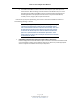
SATA 2.5 Test Adapter User Manual The third example shows a SATA 2.5 Plug TPA used to test a host: Physical Links Under Test Laboratory Sourced Signal SATA 2.5 Plug TPA Laboratory Load P a g e | 12 © 2010, 2011 Wilder Technologies, LLC Document No. 910‐0011‐000 Rev.
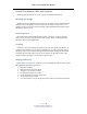
SATA 2.5 Test Adapter User Manual The fourth example shows two SATA 2.5 Plug TPAs used for testing a SATA cable: Physical Links Under Test Mated Connectors SATA 2.5 Plug TPA Laboratory Sourced Signal/Load SATA Cable SATA 2.5 Plug TPA Mated Connectors Physical Links Under Test P a g e | 13 © 2010, 2011 Wilder Technologies, LLC Document No. 910‐0011‐000 Rev.
SATA 2.5 Test Adapter User Manual The fifth example shows one SATA 2.5 Plug TPA and one SATA 2.5 Receptacle TPA used for testing a SATA extension cable: Physical Links Under Test Mated Connectors SATA 2.5 Plug TPA SATA Extension Cable Laboratory Sourced Signal/Load SATA 2.5 Receptacle TPA Physical Links Under Test P a g e | 14 © 2010, 2011 Wilder Technologies, LLC Document No. 910‐0011‐000 Rev.
SATA 2.5 Test Adapter User Manual Calibration The SATA 2.5 Plug and Receptacle Test Adapters are passive components. Therefore, calibration for the errors generated must occur within the test instrumentation that drives the SATA receiver device or looks at the response of the SATA transmitter device. The SATA2.5‐TPA‐C‐2X cable is used to provide 2X‐THRU functionality. The SATA2.5‐TPA‐C‐1X cable provides 1X‐THRU functionality for calibration.
SATA 2.5 Test Adapter User Manual SOLT SHORT, OPEN, LOAD, and 2X‐THRU (SOLT) are calibration standards used to compensate for errors associated with the TPA when used for Jitter measurement, TDR, TDT, and VNA testing.
SATA 2.5 Test Adapter User Manual 1XTHRU The 1X‐THRU is a calibration feature used to calibrate time domain instrumentation (for example, pre‐emphasized pulse generators or AWGs, arbitrary waveform generators). 1X‐THRU calibration compensates two error sources – cable losses and group delay: Cable Losses – Cable losses associated with the SATA 2.5 plug TPA, and its respective cabling that’s connected to the test source, consist of skin loss and, to a lesser extent, dielectric loss.
SATA 2.5 Test Adapter User Manual Mechanical and Environmental Specifications NOTE: All specifications in this manual are subject to change. Table 1. General Specifications ITEM DESCRIPTION Usage Environment Controlled indoor environment Plug Test Adapter Length (w/ standard cables) 171.7 mm +/‐ 2 mm (6.76 inches +/‐ .08 inches) (Characteristic) Receptacle Test Adapter Length (w/std. cables) 173.0 mm +/‐ 2 mm (6.81 inches +/‐ .
SATA 2.5 Test Adapter User Manual Table 2. SATA 2.
SATA 2.5 Test Adapter User Manual SATA2.5‐TPA‐P Cable Pinout The SATA2.5‐TPA‐P cables provide four SMA connectors (one lane of primary differential TX and RX). Labels clearly mark each cable or connector. The following figure refers to the pin‐ description table for the plug connector. Color ID for Differential Pair (See Table 3) 4 SMAs for High‐Speed Testing Color ID for Data Line Polarity (See Table 3) Plug Connector (See Table 3) Figure 5. Cable Connectors (SATA2.
SATA 2.5 Test Adapter User Manual Table 3. SATA 2.
SATA 2.5 Test Adapter User Manual Electrical Specifications NOTE: All specifications in this manual are subject to change. Table 4. Electrical Specifications SPECIFICATION MIN TYP MAX NOTES Insertion Loss (db), at 26.5 GHz 3 2 2X‐THRU with SATA2.5‐TPA‐C‐2X Cal cable Return Loss (GHz), at ‐20 db 6 9 2X‐THRU with SATA2.5‐TPA‐C‐2X Cal cable Insertion Loss (db), at 26.5 GHz 2 1 1X‐THRU with SATA2.5‐TPA‐C‐1X Cal cable Return Loss (GHz), at ‐20 dB 10 13 1X‐THRU with SATA2.
SATA 2.5 Test Adapter User Manual Figure 6. Typical 2X-THRU insertion loss Figure 7. Typical 2X-THRU return loss P a g e | 23 © 2010, 2011 Wilder Technologies, LLC Document No. 910‐0011‐000 Rev.
SATA 2.5 Test Adapter User Manual Figure 8. Typical 1X-THRU insertion loss Figure 9. Typical 1X-THRU return loss P a g e | 24 © 2010, 2011 Wilder Technologies, LLC Document No. 910‐0011‐000 Rev.
SATA 2.5 Test Adapter User Manual Figure 10. Typical mated pair 3 Gb/s eye diagram, with calibration (top) and without calibration (bottom) P a g e | 25 © 2010, 2011 Wilder Technologies, LLC Document No. 910‐0011‐000 Rev.
SATA 2.5 Test Adapter User Manual Figure 11. Typical mated pair 3 Gb/s eye data, with calibration (top) and without calibration (bottom). Note : 0.00e+000 results are below the resolution of the calculation. P a g e | 26 © 2010, 2011 Wilder Technologies, LLC Document No. 910‐0011‐000 Rev.
SATA 2.5 Test Adapter User Manual Figure 12. Typical mated pair 6 Gb/s eye diagram, with calibration (top) and without calibration (bottom) P a g e | 27 © 2010, 2011 Wilder Technologies, LLC Document No. 910‐0011‐000 Rev.
SATA 2.5 Test Adapter User Manual Figure 13. Typical mated pair 6 Gb/s eye data, with calibration (top) and without calibration (bottom) P a g e | 28 © 2010, 2011 Wilder Technologies, LLC Document No. 910‐0011‐000 Rev.
SATA 2.5 Test Adapter User Manual Figure 14. Typical mated pair balanced insertion loss, with calibration (top) and without calibration (bottom) P a g e | 29 © 2010, 2011 Wilder Technologies, LLC Document No. 910‐0011‐000 Rev.
SATA 2.5 Test Adapter User Manual Figure 15. Typical mated pair balanced return loss, with calibration (top) and without calibration (bottom) P a g e | 30 © 2010, 2011 Wilder Technologies, LLC Document No. 910‐0011‐000 Rev.
SATA 2.5 Test Adapter User Manual Figure 16. Typical differential TDR of TPA-P connected to TPA-R at 100ps Rise Time (Equivalent to 70ps, 20% to 80%) P a g e | 31 © 2010, 2011 Wilder Technologies, LLC Document No. 910‐0011‐000 Rev.
SATA 2.5 Test Adapter User Manual Figure 17. Typical Differential NEXT, without connector (top) and with mated connectors (bottom), adjacent differential pairs, both transmit and receive terminated at both ends P a g e | 32 © 2010, 2011 Wilder Technologies, LLC Document No. 910‐0011‐000 Rev.
SATA 2.5 Test Adapter User Manual Wilder Technologies, LLC – Limited Warranty Wilder Technologies, LLC warrants that each Test Adapter, 1) is free from defects in materials and workmanship and, 2) conforms to Wilder Technologies specifications for a period of 12 months. See Consumable and Fragile Material Warranty for exceptions to the 12 month warranty The warranty period for a Test Adapter is a specified, fixed period commencing on the date of ship from Wilder Technologies, LLC.
SATA 2.5 Test Adapter User Manual Wilder Technologies, LLC – Terms & Conditions of Sale 1. Other Documents: This Agreement may NOT be altered, supplemented, or amended by the use of any other document(s) unless otherwise agreed to in a written agreement signed by both you and Wilder Technologies, LLC. If you do not receive an invoice or acknowledgement in the mail, via e‐mail, or with your Product, information about your purchase may be obtained at support@wilder‐tech.
SATA 2.5 Test Adapter User Manual Compliance with Environmental Legislation Wilder Technologies, LLC, is dedicated to complying with the requirements of all applicable environmental legislation and regulations, including appropriate recycling and/or disposal of our products. WEEE Compliance Statement The European Union adopted Directive 2002/96/EC on Waste Electrical and Electronic Equipment (WEEE), with requirements that went into effect August 13, 2005.
SATA 2.5 Test Adapter User Manual Glossary of Terms TERMINOLOGY DEFINITION Aggressor A signal imposed on a system (i.e., cable assembly) to measure response on other signal carriers. Decibel (dB) Ten times the common logarithm (i.e. log10) of the ratio of relative powers. Informative The designation of a test that is not required for compliance but is considered important from a characterization standpoint. It is provided for informational purposes only.
SATA 2.5 Test Adapter User Manual Index 1X‐THRU, 17 Cable Bend Limits, 6 Cable Losses, 17 Cable Tension (Pull Forces), 6 Cable Twisting (Torque), 6 Calibration, 15 Care and Handling, 6 Cleaning, 8 Compliance WEEE, 35 Connections SATA2.
Visit our website at www.wilder‐tech.com Wilder Technologies, LLC 6101A East 18th Street Vancouver, WA 98661 Phone: 360‐859‐3041 Fax: 360‐859‐3105 www.wilder‐tech.com © 2010, 2011 Wilder Technologies, LLC Document No. 910‐0011‐000 Rev.