INSTALLATION AND OPERATION MANUAL Flow water heaters type POW-LCD MULTI
Before using the heater, please read the instructions carefully. In the future it will benefit by its failure-free operation for a long time. Flow water heaters series POW-LCD MULTI are intended for heating tap water. They can supply hot water to several water outlets located in different rooms. These heaters are equipped with heating coils which are directly washed by water. Such direct process of heating prevents scale formation and ensures high efficiency and speed of heating water.
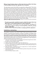
8. Remove the securing blanking plugs from water pipes. 9. Connect the heater to the water distribution system (Fig. 5 service line marked 14, outlet marked 15) 10. Switch on the water supplying the heater and check the tightness of the connections. 11. Connect the heater to the electrical wiring in accordance with Figure 4. 12. Connect the ribbon cable by inserting the plug with the proper side to the socked marked “LCD”, see (Fig. 2). 13. Put on the housing and screw it with a fastening screw. Fig.
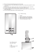
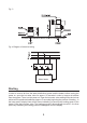
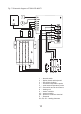
Fig. 3. Fig. 4 Diagram of electrical wiring Water heater Starting In order to remove air from the water distribution system and the heater, before turning the power on, open the hot water valve for approx. 20 seconds in order to remove air bubbles from the system. Then, turn the power on. Open the hot water valve waiting till the device has achieved full operational readiness (approx.
Use Setting the temperature of water is done by pressing one of the buttons located under the display marked “–” and “+ ” (Fig. 1) in the range from 30OC to 60OC accurate every 0.5OC. Detecting the flow greater than 2.7 l/min by the heater system will result in switching off the device. The lines of the barograph (lower part of the display) show the power with the heater heats the water.
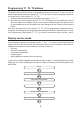
Programming T1, T2, T3 buttons The heater can save three values of temperatures selected by the user. To save, as well as select temperatures the buttons marked T1, T2, T3 are used. In order to assign the temperature value to any of the buttons (T1, T2, T3): 1. Set the desired temperature on the display by pressing “–” or “ + ” 2. Hold down any of the selected buttons ( T1, T2, T3) for approx.
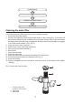
0.0 Installed power 0.0 Installation of airlock sensors Basic mode Cleaning the water filter In a situation when the filter has become fully or partially blocked: 1. Disconnect the power supply. 2. Unscrew the fastening screw located at the bottom of the housing (Fig. 1), then take off the housing holding it at such a distance from the heater that the ribbon cable connecting the display with the heater was not tightened, and then disconnect the cable by plugging it out of the socket marked “LCD” (Fig.
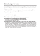
Malfunctioning of the heater Removing the causes of the malfunctioning of the heater given below is not included in the manufacturer’s guaranty. Should none of the following occur, please contact the service point. Display does not light: – disconnected ribbon cable connecting the controller board with the display (Fig. 2). – failure of the electrical wiring powering the heater. Too small flow of water: – blocked water filter. – too small water pressure. – control valve closed too tightly.
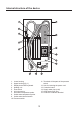
Internal structure of the device 1. Lower housing. 2. Upper housing (fig. 1) 3. Display board with keyboard. 4. Heating unit. 5. Flow switch. 6. Air lock sensors. 7. Inlet water temperature probe. 8. Outlet water temperature probe. 9. Outlet water thermal switch. 10. Pressure switch. 11. Terminals will be parts of the pressure switch. 12. Hole for inserting the power cord. 13. Controller board. 14. Supply water pipe (cold) 15. Outlet water pipe (hot) 16. Protective conductor terminal.
Fig.
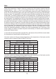
Technical data MULTI 11/13,5/15 Heater POW-MULTI 11 13,5 11 13,5 Switching power Rated power Power consumption 15 18 21 24 18 21 24 Yes kW Supply voltage Frequency MULTI 18/21/24 15 400 V 3~ Hz 50 A 18 19,4 22,2 29 31 35,5 Minimum cross-section of connecting mm2 4 x 2,5 4 x 2,5 4 x 2,5 4x4 4x4 4x6 Maximum cross-section of connecting cables mm2 Rated power of the miniature circuit breaker A 32 32 40 4 x 10 20 20 25 Minimum water resistance at 15OC Ωcm 1300 Pre
Contents of the packaging Heater POW-LCD MULTI Control valve Fastening screws with expansion plugs Gaskets Template Operating instructions Guaranty card pcs. 1 pcs. 1 pcs. 3 pcs. 2 pcs. 1 pcs. 1 pcs. 1 IMPORTANT INSTRUCTIONS CONCERNING THE DETERIORATED DEVICE Pursuant to the provisions of the Act dated 29 July 2005 on waste electric and electronic equipment, it is forbidden to put together with municipal waste the deteriorated equipment marked with the symbol of the crossed out bin.