
Brochure


64
RST 20i3
96.031.1053.0
96.031.1053.1
96.031.1055.7
96.031.1051.4
96.031.1053.9
96.032.1053.0
96.032.1053.1
96.032.1055.7
96.032.1051.4
96.032.1053.9
96.031.5053.0
96.031.5053.1
96.031.5055.7
96.031.5051.4
96.031.5053.9
96.032.5053.0
96.032.5053.1
96.032.5055.7
96.032.5051.4
96.032.5053.9
1, 2,
3
2, 1,
3
L, N,
U
N, L,
U
1, 2,
U
2, 1,
U
1, 2,
U
2, 1,
U
Power
250 V
gray
black
Power
250/400V
green
50 V
+ U
brown
Switch. funct.
250 V
light blue
Power
250 V
gray
black
Power
250/400V
green
50 V
+ U
brown
Switch. funct.
250 V
light blue
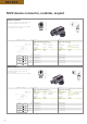
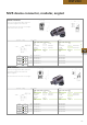
M 25 device connector, standard
Female conne ctor
Male connector
with spring clamp conn ection
Wire mm
2
Ferrules
rigid 0.5 – 2.5
fine-stranded 0.5 – 1.5 with ferrules
stranded 0.75 – 1.5 with ferrules
Term. poles 2
Thread M25 x 1.5
Gland outside
with spring clamp conn ection
Wire mm
2
Ferrules
rigid 0.5 – 2.5
fine-stranded 0.5 – 1.5 with ferrules
stranded 0.75 – 1.5 with ferrules
Term. poles 2
Thread M25 x 1.5
Gland outside
with screw conn ection
Wire mm
2
rigid
0.75 – 6.0
fine-stranded without ferrules
stranded without ferrules
Term. poles 1
Thread M25 x 1.5
Gland outside
with screw conn ection
Wire mm
2
rigid
0.75 – 6.0
fine-stranded without ferrules
stranded without ferrules
Term. poles 1
Thread M25 x 1.5
Gland outside
Correct positioning guaranteed due to
flattened thread. Fastening with screws
from outside.
See the Technical Data for insulation
strip lengths as well as the ferrules to
be used.
For spacer rings for unlocking at the
device connectors, see Accessories.
Correct positioning guaranteed due to flattened
thread. Fastening with screws from outside. With
locking device.
See the Technical Data for insulation strip lengths.
Application Coding Color
Application Coding Color
Part No.
Part No.
Part No.
Part No.