
Installation Guide
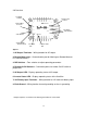

STEP 4 - Remote On/Off Switch
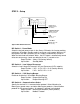
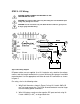
Figure 4 Remote On/Off Wiring Diagram
NOTE: If a Remote On/Off switch is not desired, install a jumper across the Remote
On/Off terminals to fix AC output on (or in standby mode). A jumper is taped to the
SureSine Lid for convenience.
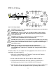
CAUTION: All low voltage conductors must be rated to 300V minimum
A remote switch can be installed to switch the SureSine AC output on/off from a
remote location allowing the SureSine to be installed in an inaccessible location
or enclosure. A single-pole, single-throw switch (SPST) is required (not included).
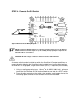
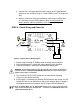
1. Using a small gauge wire (max. 1.0 mm
2
or 16 AWG, 300V min.), wire one
terminal of the Remote On/Off terminal block to one end of a SPST switch.
2. From the other contact on the switch, wire another small gauge wire to the
remaining open terminal on the Remote On/Off terminal block.
8