
Installation Guide

STEP 3 - AC Wiring
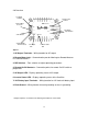
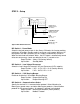
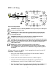
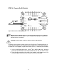
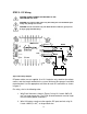
Figure 3 AC Wiring Diagram
WARNING: Complete all AC wiring BEFORE connecting a battery to the DC input to
avoid contact with AC voltage.
WARNING: Risk of electric shock. Use only approved GFCI receptacle models
listed on page 16 of this manual. Other types may fail to operate properly
connected to this unit.
when
g defines
AC Neutral.
. Use the appropriate wire color for each AC
connection as shown in figure 3.
AC Line wire to AC loads or
distribution panel as shown in figure 3.
2. Insert a 3A in-line fuse in the AC Line wire as shown in figure 3.
a
distribution panel using UL Listed 12 AWG (4 mm ) white wire.
een
wire. Check local code for appropriate earth grounding requirements.
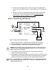
WARNING: If installing in a recreational vehicle, a ground-fault interrupter
receptacle must be installed to protect all branch circuits.
CAUTION: AC loads should not exceed 300W continuous (600W surge). Exceeding
these ratings could damage the inverter. Observe AC output voltage and frequency
markings on the SureSine. Be sure AC loads are compatible to avoid damage to
loads and/or inverter.
NOTE: The AC output is isolated, therefore AC line and neutral are
interchangeable. Use UL Listed 12AWG (4 mm
2
) black wire for AC Line and UL
Listed 12AWG (4 mm
2
) white wire for AC Neutral. The earth grounded le
AC power cables are not supplied
1. Wire a UL Listed 12AWG (4 mm
2
) black
3. Connect the AC Neutral wire to the AC device(s) or terminate at
2
4. Wire the white AC Line wire to earth ground with UL Listed 12 AWG gr
7