
Installation Guide
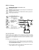

2.0 Overview
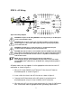
1. AC Output
Terminals
2. Remote Meter
RJ-11 Jack
3. DIP Switches
4. Remote On/Off
Terminal Contacts
6. Inverter Status
LED
5. AC Output
LED
7. 12V Battery
Input Terminals
8. Earth Ground
Terminal
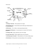
Figure 1
1. AC Output Terminals – Wiring location for AC output
2. Remote Meter Jack – Communication port for Morningstar Remote Meter or
PC Communications**.
3. DIP Switches – Four switches to adjust operating parameters
4. Remote On/Off Contacts – Connection points for remote On/Off switch or
jumper wire
5. AC Output LED – Displays operating status of AC output
6. Inverter Status LED – Displays operating status of the SureSine
7. 12V Battery Input Terminals – Wiring location for 12V lead-acid battery input
8. Earth Ground – Wiring location for earth grounding or chassis grounding
** Adapter required, not included. See Morningstar website for more details.
4