
Installation Guide
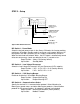

3. Connect the 12V battery positive cable (red) to the DC input positive
terminal on the SureSine using UL Listed 6 AWG (6 mm
2
) or larger red
wire.
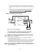
4. Wire an in-line fuse in the positive battery cable (red) no further than
12” (305 mm) from the Battery positive post. Do not connect the
battery positive cable to the battery at this time.
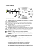
STEP 6 - Check Wiring and Power Up
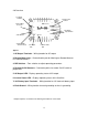
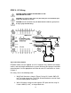
Figure 6 Complete System Wiring Diagram
1. Review steps 2 through 5. Double-check all wiring and connections.
2. Verify that the battery is wired with correct polarity to the SureSine.
3. Connect the Battery + cable (red) to the positive battery post.
WARNING: Connecting the battery to the SureSine will cause a spark at the point of
connection. There is a RISK OF EXPLOSION in hazardous areas or locations where
explosive gases have accumulated.
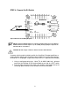
4. The SureSine STATUS LED should turn on Solid Green indicating
successful start-up and no faults.
5. If the jumper is installed or the Remote On/Off contacts are closed, the AC
Output LED will turn on Solid Green after a few seconds delay. If jumper is
removed or the contacts are open, the AC Output LED will remain off.
Note: In Standby Mode, the AC Output LED will turn on for a few seconds after start-
up. If no AC load exists, the SureSine will transition to Standby Mode and the AC
Output LED will blink Green.
10