300 Watt Pure Sine Wave Inverter Installation and Operation Manual Model SI-300-115V SI-300-220V DC Input 12 Vdc 12 Vdc AC Output 115 V @ 60 Hz 220 V @ 50 Hz 1098 Washington Crossing Road Washington Crossing, Pennsylvania 18977 USA email: info@morningstarcorp.com website: www.morningstarcorp.
Table of Contents 1.0 Safety Notes ...................................................... 3 2.0 Overview ............................................................ 4 3.0 Installation.......................................................... 5 4.0 Operation ......................................................... 11 5.0 Protections ....................................................... 12 6.0 Maintenance .................................................... 13 7.0 Warranty ................................
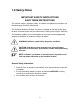
1.0 Safety Notes IMPORTANT SAFETY INSTRUCTIONS SAVE THESE INSTRUCTIONS This manual contains important safety, installation and operating instructions for the Morningstar SureSine-300 Inverter. The SureSine produces voltages and currents capable of causing severe injury or death. Extreme caution must be taken when installing and using the SureSine. The following symbols are used throughout this manual to indicate potentially dangerous conditions or important safety instructions.
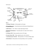
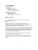
2.0 Overview 1. AC Output Terminals 8. Earth Ground Terminal 2. Remote Meter RJ-11 Jack 7. 12V Battery Input Terminals 3. DIP Switches 4. Remote On/Off Terminal Contacts 5. AC Output LED 6. Inverter Status LED Figure 1 1. AC Output Terminals – Wiring location for AC output 2. Remote Meter Jack – Communication port for Morningstar Remote Meter or PC Communications**. 3. DIP Switches – Four switches to adjust operating parameters 4.
3.0 Installation Required Tools: Wire cutters / strippers Drill and 1/8” (3 mm) drill bit Philips and Flat-head screw drivers Required Parts (not included): 3A AC in-line fuse 100A DC in-line fuse Toggle switch (if remote switch is used) STEP 1 - Mounting CAUTION - To prevent fire, do not mount in zero-clearance compartment. Overheating may result. Locate the SureSine on a surface that is protected from direct sun, high temperatures, corrosive fumes, and water.
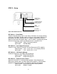
STEP 2 – Setup UP Comm. Select DOWN: Meterbus UP: Modbus DOWN LVD Warning Beeper DOWN: Beeper ON UP: Beeper OFF LVD DOWN: 11.5 V UP: 10.5 V Power Mode DOWN: Always On UP: Standby Figure 2 DIP Switch Functions DIP Switch 1 - Power Mode Select the desired power mode. In the Always ON mode, the inverter provides continuous AC output. Standby mode is an energy saving mode. When an AC load greater than 8W is detected, the AC Output is automatically turned on.
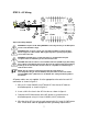
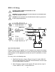
STEP 3 - AC Wiring Figure 3 AC Wiring Diagram WARNING: Complete all AC wiring BEFORE connecting a battery to the DC input to avoid contact with AC voltage. WARNING: Risk of electric shock. Use only approved GFCI receptacle models listed on page 16 of this manual. Other types may fail to operate properly when connected to this unit. WARNING: If installing in a recreational vehicle, a ground-fault interrupter receptacle must be installed to protect all branch circuits.
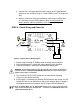
STEP 4 - Remote On/Off Switch Figure 4 Remote On/Off Wiring Diagram NOTE: If a Remote On/Off switch is not desired, install a jumper across the Remote On/Off terminals to fix AC output on (or in standby mode). A jumper is taped to the SureSine Lid for convenience. CAUTION: All low voltage conductors must be rated to 300V minimum A remote switch can be installed to switch the SureSine AC output on/off from a remote location allowing the SureSine to be installed in an inaccessible location or enclosure.
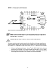
STEP 5 - DC Wiring CAUTION: DO NOT CONNECT THE BATTERY TO THE SURESINE ON THIS STEP! CAUTION: Use nominal 12Vdc input only. Exceeding the 15.5V maximum input voltage may damage the inverter. CAUTION: Use UL Listed wire only. The Earth Ground conductor (green) must be larger gauge than DC wiring. Figure 5 DC Wiring Diagram DC power cables are not supplied. Use UL Listed wire only; rated for the voltage, current, and wire length needed for the system. Minimum wire gauges have been recommended.
3. Connect the 12V battery positive cable (red) to the DC input positive terminal on the SureSine using UL Listed 6 AWG (6 mm2) or larger red wire. 4. Wire an in-line fuse in the positive battery cable (red) no further than 12” (305 mm) from the Battery positive post. Do not connect the battery positive cable to the battery at this time. STEP 6 - Check Wiring and Power Up Figure 6 Complete System Wiring Diagram 1. Review steps 2 through 5. Double-check all wiring and connections. 2.
4.0 Operation 4.1 On/Off/Standby Modes On – AC output always on unless the battery is too low or a fault exists Off – AC output off Standby – The AC output will remain off until an AC load greater than 8 Watts is detected. When the AC load falls below 8 Watts, the AC output is turned off. 4.
5.0 Protections 5.1 Low Voltage Disconnect (LVD) – The SureSine will disconnect AC Output when the battery discharges below the LVD setpoint (after a four minute delay). AC Output will resume when the battery has recharged to Low Voltage Reconnect (LVR) setpoint. The LVD/LVR thresholds are adjustable using DIP switch 2. See the Installation, Step 2 section for details. Audible LVD Warnings: The SureSine will beep four (4) times when the battery discharges to the LVD Warning threshold voltage.
6.0 Maintenance 6.1 General Care The SureSine should be mounted in a location out of direct sunlight with plenty of airflow for proper cooling. The exterior surfaces can be cleaned with a damp cloth as needed. Do not apply power if the SureSine case is cracked or damaged. 6.2 Annual Inspection 1. 2. 3. 4. 5. Tighten all terminals to avoid resistive connections. Check all system fuses. Inspect for broken wires, frayed wire insulation, and corroded conductors. Inspect for dirt, insects, nests.
7.0 Warranty The SureSine-300 is warranted to be free from defects in material and workmanship for a period of TWO (2) years from the date of shipment to the original end user. Morningstar will, at its option, repair or replace any such defective products. CLAIM PROCEDURE Before requesting warranty service, check the Operator’s Manual to be certain that there is a fault with the SureSine. Return the defective product to your authorized Morningstar distributor with shipping charges prepaid.
8.0 Technical Specifications SI-300-220V SI-300-115V Electrical AC Output Voltage (RMS) Nominal Power Rating Peak Power Rating 220V +/- 10% 115V +/- 10% 300 Watts @ 25°C 300 Watts @ 25°C 600 Watts @ 25°C (15 min) DC Input Voltage 10.0V – 15.5V Self Consumption (AC Output OFF) 25 mA Self Consumption (AC Output ON) 450 mA AC Output Frequency 50 Hz +/- 0.1% Peak Efficiency 60 Hz +/- 0.
Approved GFCI Receptacles Manufacturer Cooper - Eagle Cooper - Eagle Leviton Leviton Leviton Leviton Model XGF15 XGF20 8598 8599 8898 8899 16