Crystalline Silicon PV Module Installation Manual 1. Introduction 1.1 Purpose 1.2 Limitation of Liability 1.3 Precautions for Installation 2. Safety 2.1 General Safety 2.2 Installation Safety 3. Mechanical Installation 3.1 Installation Condition 3.2 Installation Methods 4. Electrical Installation 4.1 Installation Condition 4.2 Grounding 5. Maintenance Chint Solar (Zhejiang) Co.,Ltd. | Add:1335 Bin’an Road,Binjiang District,Hangzhou | P.
1. Introduction 1.1 Purpose This document provides detailed instructions and valuable safety information regarding the installation, electrical connection, and maintenance of following Chint Solar Crystalline Photovoltaic modules: CHSM6610M CHSM6610M(BL) CHSM6610M/HV CHSM6610P CHSM6610P(BL) CHSM6610P/HV CHSM6612M CHSM6612M/HV CHSM72M-HC CHSM6612P CHSM6612P/HV CHSM60M-HC CHSM60P-HC CHSM72P-HC All the instructions should be read and understood before installation.
c) After unpacking the modules should be installed that day as far as possible. It’s recommended to take the right amount of modules according to the progress of the project every day. Due to the modules piling on the ground after unpacking, in case of heavy rain and other inclement weather which has the potential risk to be a long soak in water can affect product reliability, such as typhoons and other modules in case of inclement weather is not installed which may be torn away.
2. Safety 2.1 General Safety 2.1.1 Consult and follow local codes and other applicable laws concerning required permitting as well as installation & inspection requirements, rules, and regulations. 2.1.2 2.1.3 2.1.4 2.1.5 PV modules should be installed and maintained by qualified personnel. Use the same performance modules within a given series. Follow all safety precautions of all components used in the system. Do not shade portions of the PV module surface from the sun for a long period of time.
2.2.7 Do not unplug the connector under load. 2.2.8 Do not work alone. 2.2.9 Wear a safety belt if working far above the ground. 2.2.10 Do not wear metallic jewelry, which can cause electric shock, while installing or troubleshooting the PV system. 2.2.11 Follow the safety regulations for any and all other system components, including wires, connectors, charging regulators, batteries, inverters, etc. 2.2.12 Do not expose wires to direct sunlight. Use UV-resistant cable. 2.2.
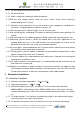
materials should be higher than Class C. 3.1.6 To maintain the modules’ fire performance type 1(for US market), it could be possible to achieve the Class A system fire rating, with the Class A class racking system. 3.2 Installation Methods 3.2.1 Bolting through the mounting holes All modules (excluding the double glass module) must be securely fastened with at least 4 bolts ( Figure a and Figure b).
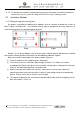
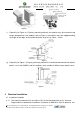
Fig c 3.2.2 Clamping on the frame surface 3.2.2.1 Single glass module Modules can be laid either across the supporting bars (Figure d & f) or parallel to the edge of frame (Figure e & g) . Fig d Fig f Fig e Fig g Remark: 1) The length of supporting bars must be longer than the length of module frame, otherwise please confirm with our product team to get approval. Chint Solar (Zhejiang) Co.,Ltd. | Add:1335 Bin’an Road,Binjiang District,Hangzhou | P.
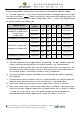
2) As for above figure d, the solid red rectangles indicate primary clamp installation positions and the center positions of long frames where clamps can be added for additional support. 3) Illustrations (figure d、e、f、g) of the four different methods for clamping modules on the frame with aluminum clamps. “ ” means the aluminum clamp’s permissible clamping range. The recommended installation position shows as below table. Note: “---” means Fig f &Fig g methods will be not suitable for the module type.
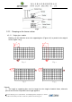
Figure h f) Figure i Especially for Figure e & Figure g mounting method, the modules may be mounted using clamps designed for solar modules refer to Figure j, the modules must be supported along the length of the edge, and should overlap the array rail by 10mm – 14mm Figure j g) Especially for Figure f & Figure g mounting method: the recommended mechanical load on panels is less than 2400Pa, and this method is only suitable for 45mm frame module series. Figure k 4 Electrical Installation 4.
temperature of 25℃. 4.1.2 The maximum system voltage of all the IEC & UL standard module series is 1000V. The 1500V standard products are also available according to the requirements). 4.1.3 Connect quantity of modules that match the voltage specifications of the inverters used in system. Modules must not be connected together to create a voltage higher than the permitted maximum system voltage under the lowest local temperature conditions. 4.1.
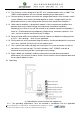
regulations and standards before work is started. 4.2.2 Use the marked 5.5 mm grounding holes to ground the anodized frame. Use one M5 nut, two M5 cut washers, one M5 plain washer, one M5 spring washer, and one M5 bolt and the copper wire. All nuts, bolts, and washers are type M5 and should be made of stainless steel (Fig. (n) ). 4.2.3 Put the bolt through the cup washer and wrap the copper wire around the bolt. (Note that the copper wire cannot be attached directly to the aluminum.) 4.2.
5.5.4 Do not clean broken glass or modules with broken lines or exposed wires, as it may cause the electric shock. CHINT SOLAR (ZHEJIANG) Co., Ltd. Add: 1335 Bin’an Rd, Binjiang District, Hangzhou, China 310053 Tel: 86-571-5603 1888 Fax: 86-571-5603 2333 http://www.astronergy.com Chint Solar (Zhejiang) Co.,Ltd. | Add:1335 Bin’an Road,Binjiang District,Hangzhou | P.C: 310053 Tel: 0086-571-5603 1888 | Fax: 086-571-5603 2316 | Website: www.astronergy.