
Installation Guide
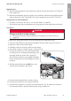
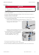
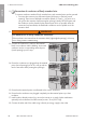
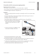
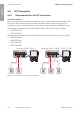
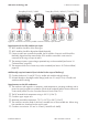
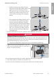
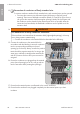
Table Of Contents
- Installation Manual
- Legal Provisions
- Table of Contents
- 1 Information on this Document
- 2 Safety
- 3 Scope of Delivery
- 4 Product Overview
- 5 Mounting
- 6 Electrical Connection
- 7 Commissioning
- 8 Disconnecting the Inverter from Voltage Sources
- 9 Decommissioning the Inverter
- 10 Technical Data
- 11 Compliance Information
- 12 Contact
- Instrucciones de instalación
- Disposiciones legales
- Índice
- 1 Indicaciones sobre este documento
- 2 Seguridad
- 3 Contenido de la entrega
- 4 Vista general del producto
- 5 Montaje
- 6 Conexión eléctrica
- 7 Puesta en marcha
- 8 Desconexión del inversor de la tensión
- 9 Puesta fuera de servicio del inversor
- 10 Datos técnicos
- 11 Información de cumplimiento
- 12 Contacto
- Instructions d’installation
- Dispositions légales
- Table des matières
- 1 Remarques relatives à ce document
- 2 Sécurité
- 3 Contenu de la livraison
- 4 Vue d’ensemble des produits
- 5 Montage
- 6 Raccordement électrique
- 7 Mise en service
- 8 Mise hors tension de l’onduleur
- 9 Mise hors service de l’onduleur
- 10 Caractéristiques techniques
- 11 Informations sur le respect des spécifications
- 12 Contact

6 Electrical Connection
SMA Solar Technology AG
Installation Manual SBxx-1SP-US-41-IA-xx-10 43
Procedure:
1.
DANGER
Danger to life due to high voltages
• Ensure that the inverter is disconnected from all voltage sources (see Section8,
page61).
2. Remove the sealing plug from the enclosure opening for connecting the outlet for secure
power supply operation.
3. Insert the conduit fitting into the opening and tighten from the inside using the counter nut.
4. Attach the conduit to the conduit fitting.
5. Guide the conductors into the inverter.
6. Connect the equipment grounding conductor of the outlet for secure power supply operation
to an equipment grounding terminal:
• Strip the insulation of the equipment grounding conductor by 18mm (0.71in).
• Insert the screw through the spring washer, the
clamping bracket and the washer.
• Guide the equipment grounding conductor between the washer and clamping bracket
and tighten the screw (TX 25) (torque: 6Nm ± 0.3Nm (53.10in-lb ± 2.65in-lb)).
7. Plug the terminal block for connecting the outlet for
secure power supply operation into the SPS slot in
the inverter and tighten it with a flat-blade
screwdriver (blade width: 4mm (
5
/
32
in)).
AC-out
SPS
L N
1
2
8. Ensure that the terminal block is securely in place.
9. Strip off the conductor insulation by max. 15mm (0.59in).
10. In the case of finely stranded wire, provide the conductors L and N with a bootlace ferrule.
ENGLISH