
Installation Guide
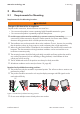
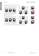
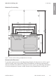
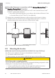
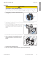
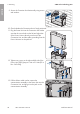
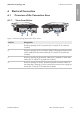
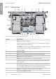
Table Of Contents
- Installation Manual
- Legal Provisions
- Table of Contents
- 1 Information on this Document
- 2 Safety
- 3 Scope of Delivery
- 4 Product Overview
- 5 Mounting
- 6 Electrical Connection
- 7 Commissioning
- 8 Disconnecting the Inverter from Voltage Sources
- 9 Decommissioning the Inverter
- 10 Technical Data
- 11 Compliance Information
- 12 Contact
- Instrucciones de instalación
- Disposiciones legales
- Índice
- 1 Indicaciones sobre este documento
- 2 Seguridad
- 3 Contenido de la entrega
- 4 Vista general del producto
- 5 Montaje
- 6 Conexión eléctrica
- 7 Puesta en marcha
- 8 Desconexión del inversor de la tensión
- 9 Puesta fuera de servicio del inversor
- 10 Datos técnicos
- 11 Información de cumplimiento
- 12 Contacto
- Instructions d’installation
- Dispositions légales
- Table des matières
- 1 Remarques relatives à ce document
- 2 Sécurité
- 3 Contenu de la livraison
- 4 Vue d’ensemble des produits
- 5 Montage
- 6 Raccordement électrique
- 7 Mise en service
- 8 Mise hors tension de l’onduleur
- 9 Mise hors service de l’onduleur
- 10 Caractéristiques techniques
- 11 Informations sur le respect des spécifications
- 12 Contact

5 Mounting
SMA Solar Technology AG
Installation Manual SBxx-1SP-US-41-IA-xx-10 27
Procedure:
1.
CAUTION
Risk of injury due to damaged cables
There may be power cables or other supply lines (e.g. gas or water) routed in the wall.
• Ensure that no lines are laid in the wall which could be damaged when drilling holes.
2. Ensure that the DC load-break switch of the inverter
is in the O position.
3. Opening the Connection Unit Unscrew all six screws (TX25) and carefully remove the
enclosure lid toward the front.
4. Unscrew the two screws on the right and left side of
the PowerUnit (TX25). As a result, the Power Unit
and the Connection Unit are not connected to one
another.
5. Disconnect the Connection Unit from the Power Unit.
6. Align the Connection Unit horizontally on the wall
and mark the position of the drill holes using the
brackets.
7. Drill the holes in the marked positions.
8. Insert screw anchors into the drill holes if the support surface requires them.
ENGLISH