
Installation Guide
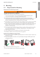
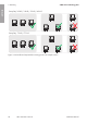
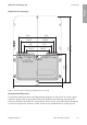
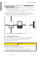
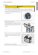
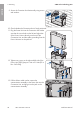
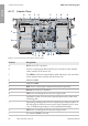
Table Of Contents
- Installation Manual
- Legal Provisions
- Table of Contents
- 1 Information on this Document
- 2 Safety
- 3 Scope of Delivery
- 4 Product Overview
- 5 Mounting
- 6 Electrical Connection
- 7 Commissioning
- 8 Disconnecting the Inverter from Voltage Sources
- 9 Decommissioning the Inverter
- 10 Technical Data
- 11 Compliance Information
- 12 Contact
- Instrucciones de instalación
- Disposiciones legales
- Índice
- 1 Indicaciones sobre este documento
- 2 Seguridad
- 3 Contenido de la entrega
- 4 Vista general del producto
- 5 Montaje
- 6 Conexión eléctrica
- 7 Puesta en marcha
- 8 Desconexión del inversor de la tensión
- 9 Puesta fuera de servicio del inversor
- 10 Datos técnicos
- 11 Información de cumplimiento
- 12 Contacto
- Instructions d’installation
- Dispositions légales
- Table des matières
- 1 Remarques relatives à ce document
- 2 Sécurité
- 3 Contenu de la livraison
- 4 Vue d’ensemble des produits
- 5 Montage
- 6 Raccordement électrique
- 7 Mise en service
- 8 Mise hors tension de l’onduleur
- 9 Mise hors service de l’onduleur
- 10 Caractéristiques techniques
- 11 Informations sur le respect des spécifications
- 12 Contact

5 Mounting
SMA Solar Technology AG
Installation ManualSBxx-1SP-US-41-IA-xx-1026
Prescribed clearances in accordance with the
National Electrical Code
®
or
Canadian Electrical Code
®
CSA C22.1
Under certain conditions, the National Electrical Code
®
or the Canadian Electrical Code
®
CSA C22.1 specify greater clearances.
• Ensure that the prescribed clearances in accordance with the National Electrical Code
®
or Canadian Electrical Code
®
CSA C22.1 are adhered to.
☐ Maintain the recommended clearances to walls as well as to other inverters or objects.
☐ If multiple inverters are mounted in areas with high ambient temperatures, increase the
clearances between the inverters and ensure sufficient fresh-air supply.
700
(27.56)
600
(23.62)
500
(19.69)
500
(19.69)
500
(19.69)
500
(19.69)
Figure 6 : Recommended clearances(Dimensions in mm (in))
5.2 Mounting the Inverter
Additionally required mounting material (not included in the scope of delivery):
☐ 2 Three screws suitable for the support surface (diameter: 8mm (5/16in))
☐ Two washers suitable for the screws
☐ Where necessary, two screw anchors suitable for the support surface and the screws
CAUTION
Risk of injury due to weight of product
Injuries may result if the product is lifted incorrectly or dropped while being transported or when
attaching it to or removing it from the wall mounting bracket.
• Transport and lift the product carefully. Take the weight of the product into account.
• Wear suitable personal protective equipment for all work on the product.
ENGLISH