
Installation Guide
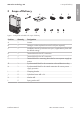
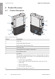
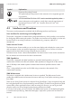
Table Of Contents
- Installation Manual
- Legal Provisions
- Table of Contents
- 1 Information on this Document
- 2 Safety
- 3 Scope of Delivery
- 4 Product Overview
- 5 Mounting
- 6 Electrical Connection
- 7 Commissioning
- 8 Disconnecting the Inverter from Voltage Sources
- 9 Decommissioning the Inverter
- 10 Technical Data
- 11 Compliance Information
- 12 Contact
- Instrucciones de instalación
- Disposiciones legales
- Índice
- 1 Indicaciones sobre este documento
- 2 Seguridad
- 3 Contenido de la entrega
- 4 Vista general del producto
- 5 Montaje
- 6 Conexión eléctrica
- 7 Puesta en marcha
- 8 Desconexión del inversor de la tensión
- 9 Puesta fuera de servicio del inversor
- 10 Datos técnicos
- 11 Información de cumplimiento
- 12 Contacto
- Instructions d’installation
- Dispositions légales
- Table des matières
- 1 Remarques relatives à ce document
- 2 Sécurité
- 3 Contenu de la livraison
- 4 Vue d’ensemble des produits
- 5 Montage
- 6 Raccordement électrique
- 7 Mise en service
- 8 Mise hors tension de l’onduleur
- 9 Mise hors service de l’onduleur
- 10 Caractéristiques techniques
- 11 Informations sur le respect des spécifications
- 12 Contact

4 Product Overview
SMA Solar Technology AG
Installation Manual SBxx-1SP-US-41-IA-xx-10 15
Position Designation
I Additional type label
The additional type label must remain permanently attached to the prod-
uct. You will find the following information on the additional type label:
• Device type (Model)
• Inverter serial number (Serial number device or S/N device)
• Identification key (PIC) for registration in Sunny Portal
• Registration ID (RID) for registration in Sunny Portal
• WLAN password (WPA2-PSK) for the direct connection to the user
interface of the inverter via WLAN
J Display
The display shows the current operating data and events or errors.
K LEDs
The LEDs indicate the operating state of the inverter.
4.2 Symbols on the Product
Symbol Explanation
Beware of electrical voltage
The product operates at high voltages.
Beware of hot surface
The product can get hot during operation.
Observe the documentation
Observe all documentation supplied with the product.
Observe the documentation
Together with the red LED, this symbol indicates an error.
Inverter
Together with the green LED, this symbol indicates the operating state of the in-
verter.
Data transmission
Together with the blue LED, this symbol indicates the status of the network con-
nection.
ENGLISH