
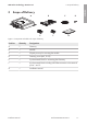
Installation Guide

5 Connection
SMA Solar Technology America LLC
Installation manualRoofCommKit-P2-US-IA-xx-1114
5 Connection
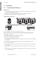
5.1 Connecting the Gateway
Requirements:
☐ If several Gateways are present in the system, these have to be connected to each other prior
connection to the module in the inverter.
☐ A maximum of threeGateways can be connected to one module in the inverter.
☐ A terminator must be plugged into the last gateway in the row.
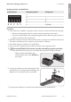
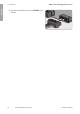
Cabling plan of the Gateways:
B A
_
+B A
_
+ B A
_
+ B A
_
+B A
_
+ B A
_
+
B A
_
+B A
_
+
+− B A S
Figure 4 : Cabling plan of the Gateways with module in the inverter
Cable requirements for the communication cable between Gateway and inverter:
☐ Number of conductors: 4
☐ Conductor cross-section: at least 0.22mm² (24AWG)
☐ Maximum external diameter: 8mm (0.31in)
☐ Maximum cable length: 305m (1000ft)
☐ The conductors should be twisted pairs if the total length of the communication cable exceeds
61m (200ft).
☐ The conductors should be shielded if the cable is laid in a nonmetallic cable raceway.
☐ UV-resistant for outdoor use
☐ The conductors lengths in the inverter must be as short as possible. This prevents contact with
live conductors.
☐ If the conductor is to be installed without conduit, the conductor has to be suited for outdoor
use.
☐ If the conductor is to be installed in a conduit together with live conductors, the conductor has
to be insulated for 600V.
ENGLISH