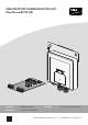
SMA ROOFTOP COMMUNICATION KIT (RoofCommKit-P2-US) ENGLISH Installation manual FRANÇAIS Instructions d’installation ESPAÑOL Instrucciones de instalación RoofCommKit-P2-US-IA-xx-11 | 112604-00.01 | Version 1.
Legal Provisions SMA Solar Technology America LLC ENGLISH Legal Provisions No part of this document may be reproduced, stored in a retrieval system, or transmitted, in any form or by any means, be it electronic, mechanical, photographic, magnetic or otherwise, without the prior written permission of SMA Solar Technology America LLC. Neither SMA Solar Technology America LLC nor SMA Solar Technology Canada Inc.
ENGLISH General Warnings SMA Solar Technology America LLC General Warnings WARNING All electrical installations must be carried out in accordance with the local electrical standards and the National Electrical Code® ANSI/NFPA 70 or the Canadian Electrical Code® CSA C22.1.
Table of Contents SMA Solar Technology America LLC ENGLISH Table of Contents 1 2 Information on this Document................................................. 5 1.1 1.2 1.3 1.4 1.5 5 5 5 5 6 Validity ........................................................................................................................ Target Group.............................................................................................................. Content and Structure of this Document ....................
1 1 Information on this Document ENGLISH SMA Solar Technology America LLC Information on this Document 1.1 Validity This document is valid for: • RoofCommKit-P2-US (SMA Rooftop Communication Kit) 1.2 Target Group The tasks described in this document must only be performed by qualified persons.
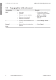
1 Information on this Document ENGLISH 1.5 SMA Solar Technology America LLC Typographies in the document Typography Use Example bold • • • • • > • Connects several elements to be selected • Select Settings > Date. [Button] [Key] • Button or key to be selected or pressed • Select [Enter]. 6 Messages Terminals Elements on a user interface Elements to be selected Elements to be entered RoofCommKit-P2-US-IA-xx-11 • Connect the insulated conductors to the terminals X703:1 to X703:6.
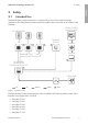
2 Safety 2 2.1 ENGLISH SMA Solar Technology America LLC Safety Intended Use The SMA Rooftop Communication Kit is a communication set for TS4 module technology components. The SMA Rooftop Communication Kit enables direct connection of the inverter to the Gateway. SUNNY PORTAL/ SUNNY PLACES PV GENERATOR ... GATEWAY (GTWY) TS4 INTERNET ... ...
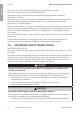
2 Safety SMA Solar Technology America LLC ENGLISH The inverter still complies with the standard after the product has been installed. The product is approved for the US and Canadian market. All components must remain within their permitted operating ranges and their installation requirements at all times. Use this product only in accordance with the information provided in the enclosed documentation and with the locally applicable standards and directives.
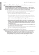
ENGLISH 2 Safety SMA Solar Technology America LLC NOTICE Damage to the enclosure seal in subfreezing conditions If you open the inverter when temperatures are below freezing, the enclosure seals can be damaged. This can lead to moisture entering the inverter. • Only open the inverter if the ambient temperature is not below 0°C (32°F). • If a layer of ice has formed on the enclosure seal when temperatures are below freezing, remove it prior to opening the inverter (e.g. by melting the ice with warm air).
2 Safety SMA Solar Technology America LLC ENGLISH After installation of the Rooftop Communication Kit, the secure power supply operation is no longer supported. The Rooftop Communication Kit supports the Rapid Shutdown function. A rapid shutdown is triggered in the event of a grid failure or an interruption of the AC supply of the inverter. Thus the supply of the outlet for secure power supply operation is no longer possible.
3 ENGLISH 3 Scope of Delivery SMA Solar Technology America LLC Scope of Delivery A C B E F D G Figure 2 : Components included in the scope of delivery Position Quantity Designation A 1 Gateway B 1 Module C 1 20-pole pin strip for mounting the module D 1 Fastening screw (M5, TX 25) E 1 5-pole terminal block for connecting the Gateway F 1 4-pole terminal block including 6.8 kOhm resistance in the terminal points 1 and 2.
4 Mounting ENGLISH 4 SMA Solar Technology America LLC Mounting 4.1 Mounting position A X1 X2 DISP LAY FCC IC: 94ID: SV 40A F-KP -KP20 BAT Max . 30V DC MFR USB A B B Figure 3 : Communication assembly in the inverter with mounting position for the module Position Designation A Communication assembly B Module slot M2 4.2 Installing the Module Procedure: 1. Remove the enclosure lid of the DC Connection Unit. Unscrew all screws (TX25) and remove the enclosure lid towards the front. 2.
4 Mounting ENGLISH SMA Solar Technology America LLC • Guide the three guide pins on the communication assembly through the holes in the module. • Carefully push the module down on the upper edge and on the connection sockets until it audibly snaps into both side locking tabs of the communication assembly. The plug on the back of the module is automatically pushed into the socket terminal strip of the communication assembly. CLICK 5. Tighten the fastening screw (TX25, torque: 1.5 Nm (13 in-lb)).
5 Connection ENGLISH 5 5.1 SMA Solar Technology America LLC Connection Connecting the Gateway Requirements: ☐ If several Gateways are present in the system, these have to be connected to each other prior connection to the module in the inverter. ☐ A maximum of three Gateways can be connected to one module in the inverter. ☐ A terminator must be plugged into the last gateway in the row.
5 Connection ENGLISH SMA Solar Technology America LLC Assignment of the terminal block: Terminal block A B C D E Clamping position Assignment A - B + C B D A E S (Shield) Procedure: 1. If the conductor is installed in a separate conduit, mount the conduit to the enclosure opening: • Remove the sealing plugs from the network connection opening on the inverter. • Insert the conduit fitting into the opening and tighten from the inside using the counter nut.
5 Connection -- SI --R S- P --S S4 R ENGLISH 8. Plug the terminal block into the jack RS485 on the module.
6 6 Commissioning the Rooftop Communication Kit ENGLISH SMA Solar Technology America LLC Commissioning the Rooftop Communication Kit Limited view of the data in Sunny Portal due to incorrect router configuration Due to an incorrect router configuration, the view of system data in Sunny Portal or in Sunny Places is only possible to a limited extent. For unlimited access to system data in Sunny Portal or in Sunny Places, the router must be configured as described in the following.
7 Disposing of the Product ENGLISH 7 SMA Solar Technology America LLC Disposing of the Product • Dispose of the product in accordance with the locally applicable disposal regulations for electronic waste.
8 ENGLISH 8 Contact SMA Solar Technology America LLC Contact If you have technical problems with our products, please contact the SMA Service Line.
9 Compliance Information ENGLISH 9 SMA Solar Technology America LLC Compliance Information FCC Compliance This device complies with Part 15 of the FCC Rules and with Industry Canada licence-exempt RSS standard(s). Operation is subject to the following two conditions: 1. this device may not cause harmful interference, and 2. this device must accept any interference received, including interference that may cause undesired operation.
SMA Solar Technology America LLC Disposiciones legales Queda prohibida la reproducción total o parcial de este documento, así como su almacenamiento en un sistema de recuperación y toda transmisión electrónica, mecánica, fotográfica, magnética o de otra índole sin previa autorización por escrito de SMA Solar Technology America, LLC. Ni SMA Solar Technology America, LLC ni SMA Solar Technology Canada Inc.
Advertencias generales SMA Solar Technology America LLC Advertencias generales ADVERTENCIA ESPAÑOL Todas las instalaciones eléctricas deben realizarse conforme a la normativa local vigente y al código National Electrical Code® ANSI/NFPA 70 o al Canadian Electrical Code® CSA C22.1.
Índice SMA Solar Technology America LLC Índice Indicaciones sobre este documento ....................................... 24 1.1 1.2 1.3 1.4 1.5 2 Área de validez.......................................................................................................... Grupo de destinatarios.............................................................................................. Contenido y estructura del documento.....................................................................
1 Indicaciones sobre este documento 1 SMA Solar Technology America LLC Indicaciones sobre este documento 1.1 Área de validez Este documento es válido para: • RoofCommKit-P2-US (SMA Rooftop Communication Kit) ESPAÑOL 1.
1 Indicaciones sobre este documento SMA Solar Technology America LLC Marcas de texto en el documento Marca de texto Uso Ejemplo Negrita • Avisos • Conexiones • Elementos de una interfaz de usuario • Elementos que deben seleccionarse • Elementos que deben introducirse • Conecte los conductores a los bornes de X703:1 a X703:6. • Introduzca 10 en el campo Minutos. > • Une varios elementos que deben seleccionarse. • Seleccione Ajustes > Fecha.
2 Seguridad 2 2.1 SMA Solar Technology America LLC Seguridad Uso previsto El SMA Rooftop Communication Kit es un kit de conmutación para los componentes de la técnica modular TS4. Das SMA Rooftop Communication Kit permite la conexión directa del inversor con el Gateway. ESPAÑOL SUNNY PORTAL/ SUNNY PLACES GENERADOR FOTOVOLTAICO ... GATEWAY (GTWY) TS4 INTERNET ... ...
Después del montaje del producto, este sigue siendo conforme a las normas. El producto está autorizado para el mercado de EE. UU. y Canadá. Deben respetarse en todo momento el rango de funcionamiento admisible y los requisitos de instalación de todos los componentes. Utilice siempre el producto de acuerdo con las indicaciones de la documentación adjunta y observe las normativas y directivas locales vigentes. Cualquier otro uso puede causarle lesiones al usuario o daños materiales.
2 Seguridad SMA Solar Technology America LLC ATENCIÓN Radiación electromagnética aumentada por la antena Durante el funcionamiento, la antena crea un campo electromagnético y puede causar perturbaciones en otros equipos (p. ej. marcapasos) por emisión de interferencias. • Las personas no deben permanecer prolongadamente a menos 20 cm (8 in) de la antena.
2 Seguridad SMA Solar Technology America LLC El Rooftop Communication Kit es compatible con la función Rapid Shutdown. El Rapid Shutdown se dispara en caso de apagón o interrupción de la alimentación de CA del inversor. De esta manera la alimentación de una toma de pared para el funcionamiento de corriente de emergencia no es posible.
3 Contenido de la entrega 3 SMA Solar Technology America LLC Contenido de la entrega A C B D ESPAÑOL E F G Imagen 2 : Componentes del contenido de la entrega Posición Cantidad Denominación A 1 Gateway B 1 Módulo C 1 Regleta de clavijas de 20 polos para el montaje del módulo D 1 Tornillo de fijación (M5, TX 25) E 1 Caja de bornes de 5 polos para la conexión de los Gateway F 1 Caja de bornes de 4 polos con 6,8 kOhm de resistencia en los puntos de embornaje 1 y 2 G 1 Instrucci
4 Montaje SMA Solar Technology America LLC 4 Montaje 4.1 Posición de montaje A ESPAÑOL X1 X2 DISP LAY FCC IC: 94ID: SV 40A F-KP -KP20 BAT Max . 30V DC MFR USB A B B Imagen 3 : Subgrupo de comunicación del inversor con posición de montaje para el módulo Posición Denominación A Subgrupo de comunicación B Ranura del módulo M2 4.2 Instalación del módulo Procedimiento: 1. Desmonte la tapa de la carcasa de la Connection Unit CC.
4 Montaje SMA Solar Technology America LLC • Conduzca los tres pasadores de guía del subgrupo de comunicación por de los orificios del módulo. ESPAÑOL • Cuidadosamente, empuje el módulo hacia abajo por el borde superior y por las hembrillas de conexión, hasta que se encaje en los dos ganchos de retención laterales del subgrupo de comunicación. De esta forma se aprieta automáticamente el conector a la parte trasera del módulo en la regleta de hembrillas del subgrupo de comunicación. CLICK 5.
5 Conexión SMA Solar Technology America LLC 5.1 Conexión Conexión de la Gateway Requisitos: ☐ Si hay disponibles varios Gateway en la instalación, estas deben conectarse entre sí antes de conectarse al módulo del inversor. ☐ Al inversor no deben conectarse más de 3 Gateway en cada módulo. ☐ En el último Gateway de la fila debe conectarse un terminador.
5 Conexión SMA Solar Technology America LLC Asignación de la caja de bornes: Caja de bornes ESPAÑOL A B C D E Punto de conexión Asignación A - B + C B D A E S (Shield) Procedimiento: 1. Si se desea tender el conductor en un conducto para cables propio, este último debe montarse en la abertura de la carcasa: • Saque el sellador de la abertura del inversor destinada a la conexión de red. • Introduzca el manguito en la abertura y colóquelo desde el interior con la contratuerca.
5 Conexión SMA Solar Technology America LLC -- SI --R 7. Asegúrese de que los conductores estén bien fijos en los puntos de embornaje de la caja de bornes. 8. Inserte en el módulo una caja de bornes en un conector hembra RS485.
6 Puesta en servicio del Rooftop Communication Kit 6 SMA Solar Technology America LLC Puesta en servicio del Rooftop Communication Kit Indicación limitada de datos en el Sunny Portal por la falta de configuración de rúter ESPAÑOL Por la falta de configuración de rúter, la visualización de datos de la planta en el Sunny Portal o en Sunny Places solo será posible de manera limitada.
SMA Solar Technology America LLC 7 7 Eliminación del producto Eliminación del producto ESPAÑOL • Deseche el producto conforme a las disposiciones vigentes sobre eliminación de residuos electrónicos.
8 Contacto 8 SMA Solar Technology America LLC Contacto ESPAÑOL Si surge algún problema técnico con nuestros productos, póngase en contacto con el Servicio Técnico de SMA.
SMA Solar Technology America LLC 9 9 Información de cumplimiento Información de cumplimiento This device complies with Part 15 of the FCC Rules and with Industry Canada licence-exempt RSS standard(s). Operation is subject to the following two conditions: 1. this device may not cause harmful interference, and 2. this device must accept any interference received, including interference that may cause undesired operation.
Dispositions légales SMA Solar Technology America LLC Dispositions légales FRANÇAIS Aucune partie du présent document ne peut être reproduite, stockée dans un système d’extraction de données ou transmise par quelque moyen que ce soit (électroniquement, mécaniquement, par photocopie ou par enregistrement) sans l’accord écrit préalable de SMA Solar Technology America, LLC. SMA Solar Technology America, LLC et SMA Solar Technology Canada Inc.
Mises en garde générales SMA Solar Technology America LLC Mises en garde générales Toutes les installations électriques doivent être réalisées conformément aux normes électriques en vigueur sur le site et au National Electrical Code® ANSI/NFPA 70 ou au Canadian Electrical Code® CSA C22.1.
Table des matières SMA Solar Technology America LLC Table des matières 1 Remarques relatives à ce document....................................... 43 1.1 1.2 1.3 1.4 1.5 2 Champ d’application ................................................................................................. Groupe cible .............................................................................................................. Contenu et structure du document .............................................................
1 Remarques relatives à ce document SMA Solar Technology America LLC 1 Remarques relatives à ce document 1.1 Champ d’application Ce document est valable pour les : • RoofCommKit-P2-US (SMA Rooftop Communication Kit) 1.2 Groupe cible 1.3 FRANÇAIS Les opérations décrites dans le présent document doivent uniquement être réalisées par un personnel qualifié.
1 Remarques relatives à ce document 1.5 Format SMA Solar Technology America LLC Formats utilisés dans le document Utilisation Exemple gras • Messages • Raccordements • Éléments d’une interface utilisateur • Éléments devant être sélectionnés • Éléments devant être saisis • Raccorder les conducteurs isolés aux bornes X703:1 à X703:6. • Saisissez 10 dans le champ Minutes. > • Associe plusieurs éléments que vous devez sélectionner • Sélectionnez Réglages > Date.
2 Sécurité SMA Solar Technology America LLC 2 Sécurité 2.1 Utilisation conforme Le SMA Rooftop Communication Kit est un kit de communication pour les composants de technique modulaire TS4. Le SMA Rooftop Communication Kit permet de connecter directement l’onduleur à la Gateway. SUNNY PORTAL/ SUNNY PLACES GÉNÉRATEUR PHOTOVOLTAÏQUE ... INTERNET FRANÇAIS GATEWAY (GTWY) TS4 ... ...
2 Sécurité SMA Solar Technology America LLC FRANÇAIS Après l’intégration du produit dans l’onduleur, la conformité normative continue d’être assurée. Le produit est homologué pour les marchés américain et canadien. La plage de fonctionnement autorisée et les exigences pour les installations de tous les composants doivent être respectées en toutes circonstances. Utilisez ce produit exclusivement en conformité avec la documentation fournie ainsi qu’avec les normes et directives en vigueur sur le site.
2 Sécurité SMA Solar Technology America LLC PRUDENCE Risque d’endommagement du joint du boîtier en raison du gel Si vous ouvrez l’onduleur quand il gèle, le joint pourra être endommagé. De l’humidité peut donc pénétrer dans l’onduleur. • N’ouvrez l’onduleur que si la température ambiante n’est pas inférieure à 0 °C (32 °F). • Si vous devez ouvrir l’onduleur quand il gèle, éliminez tout d’abord la glace qui a pu s’accumuler sur le joint du boîtier (par exemple en la faisant fondre avec de l’air chaud).
2 Sécurité SMA Solar Technology America LLC Le mode d’alimentation de secours n’est plus supporté après le montage du Rooftop Communication Kit FRANÇAIS Le Rooftop Communication Kit supporte la fonction Rapid Shutdown. En cas de panne du réseau ou d’une coupure de la tension AC de l’onduleur, la fonction Rapid Shutdown est déclenchée. L’alimentation d’une prise de courant pour le mode d’alimentation de secours n’est donc plus assurée.
3 Contenu de la livraison SMA Solar Technology America LLC 3 Contenu de la livraison A C B E F D G Figure 2 : Éléments du contenu de livraison Quantité Désignation A 1 Gateway B 1 Module C 1 Barrette à broches 20 pôles pour le montage du module D 1 Vis de fixation (M5, TX 25) E 1 Plaque à bornes 5 pôles pour le raccordement de la Gateway F 1 Plaque à bornes 4 pôles avec une résistance de 6,8 kOhm dans les points de serrage 1 et 2 G 1 Instructions d’installation Instructions
4 Montage 4 SMA Solar Technology America LLC Montage 4.1 Position de montage A X1 X2 DISP LAY FCC IC: 94ID: SV 40A F-KP -KP20 BAT Max . 30V DC MFR USB A B B FRANÇAIS Figure 3 : Groupe de communication interne à l’onduleur, avec position de montage pour le module Position Désignation A Groupe de communication B Port du module M2 4.2 Installation du module Procédure : 1. Démontez le couvercle du boîtier de la Connection Unit DC.
4 Montage SMA Solar Technology America LLC • Passez les trois axes de guidage situés sur le groupe de communication dans les trous du module. • Appliquez le module en appuyant avec précaution sur le bord supérieur et sur les prises de raccordement jusqu’à ce que vous l’entendiez s’encliqueter dans les deux ergots d’enclenchement du groupe de communication. La fiche située au dos du module s’enfonce automatiquement dans la borne femelle du groupe de communication. FRANÇAIS CLICK 5.
5 Raccordement 5 5.1 SMA Solar Technology America LLC Raccordement Raccordement de la Gateway Conditions requises : ☐ Lorsqu’il y a plusieurs Gateway dans l’installation, celles-ci doivent être reliées les unes aux autres dans l’onduleur avant le raccordement au panneau photovoltaïque. ☐ Il est interdit de raccorder plus de 3 Gateway à un module dans l’onduleur. ☐ La résistance de terminaison doit être enfichée sur la dernière Gateway de la ligne.
5 Raccordement SMA Solar Technology America LLC Plaque à bornes A B C D E Point de serrage Affectation A - B + C B D A E S (Shield) Procédure : 1. Si le conducteur est posé dans son propre tuyau à câbles, montez le tuyau à câbles dans une ouverture de boîtier : • Retirez le bouchon d’étanchéité de l’ouverture pour le raccordement au réseau au niveau de l’onduleur. • Placez le manchon dans l’ouverture et serrez-le de l’intérieur avec le contre-écrou. • Fixez le tuyau à câbles au manchon.
5 Raccordement SMA Solar Technology America LLC -- SI --R 7. Assurez-vous que les conducteurs sont bien serrés dans les points de serrage de la plaque à bornes. 8. Enfichez la plaque à bornes dans l’embase RS485 du module.
SMA Solar Technology America LLC 6 6 Mise en service du Rooftop Communication Kit Mise en service du Rooftop Communication Kit Affichage limité des données dans le Sunny Portal en raison d’une configuration incorrecte du routeur Procédure : 1. Mettez l’onduleur en service (voir les instructions de l’onduleur). 2. Lancez l’interface utilisateur de l’onduleur (voir les instructions de l’onduleur). 3. Lancez l’assistant d’installation (voir instructions de l’onduleur). 4.
7 Élimination du produit 7 SMA Solar Technology America LLC Élimination du produit • Éliminez le produit conformément aux prescriptions d’élimination en vigueur pour les déchets d’équipements électriques et électroniques.
8 Contact SMA Solar Technology America LLC 8 Contact En cas de problèmes techniques concernant nos produits, prenez contact avec le Service en Ligne de SMA. Les données suivantes sont indispensables à une assistance ciblée : • Onduleur : – Numéro de série – Version du micrologiciel – Réglages spéciaux régionaux (le cas échéant) • Description détaillée du problème Canada SMA Solar Technology Toll free for Canada / Sans frais pour le Canada : Canada Inc.
9 Informations sur le respect des spécifications 9 SMA Solar Technology America LLC Informations sur le respect des spécifications FCC Compliance FRANÇAIS This device complies with Part 15 of the FCC Rules and with Industry Canada licence-exempt RSS standard(s). Operation is subject to the following two conditions: 1. this device may not cause harmful interference, and 2. this device must accept any interference received, including interference that may cause undesired operation.
www.SMA-Solar.