
Installation Guide

PAGE 16 OF 18
MISSION SOLAR ENERGY LLC
ELECTRONIC versions are uncontrolled except when accessed directly from document control directory. Printed copies are uncontrolled unless verified against online document.
COPYRIGHT 2019 MISSION SOLAR ENERGY LLC, ALL RIGHTS RESERVED
REVISION:[ R10] 6/12/2019
RELEASE DATE: 11/16/2016
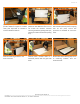
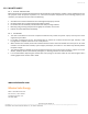
12.3 CONNECTORS
• Keep connectors dry and clean. Ensure that connector caps are hand-tight before connecting the modules.
• Do not attempt to make an electrical connection with wet, soiled, or otherwise faulty connectors.
• Avoid sunlight exposure and water immersion of the connectors. Avoid allowing connectors to rest on the ground.
• Ensure cable connectors are UL and Canadian code complaint.
• Faulty connections can result in arcs and electrical shock.
• Check that all electrical connections are securely fastened.
• Make sure that all locking connectors are fully engaged and locked.
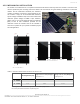
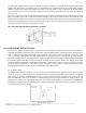
12.4 DIODES
• The junction boxes used with Mission Solar Energy modules contain bypass diodes wired in parallel with the PV cell
strings.
• In the case of partial shading, the diodes bypass the current generated by the non-shaded cells, thereby limiting
modules heating and performance losses. Bypass diodes are not over-current protection devices.
• Bypass diodes divert current from the cell strings in the event of partial shading. In the event of a known or suspected
diode failure, installers or maintenance providers should contact Mission Solar Energy.
• Never attempt to open the junction box.
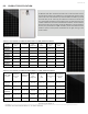
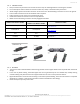
CONNECTOR MODEL NAME
ALLOWABLE MATING
CONNECTOR MODEL NAME
MANUFACTURER
PV-KBT4-EVO 2/6II-UR PV-KST4-EVO 2/6II-UR
Staubli Electrical Connectors AG
www.staubli.com
PV-KBT4/6II-UR PV-KST4/6II-UR
Staubli Electrical Connectors AG
www.staubli.com
05-8 05-8
RENHE SOLAR
www.renhesolar.com
PV-JM608 PV-JM608
Zhejiang Jiaming Tianheyuan PV Technology Co., Ltd
en.jmthy.com