
Installation Guide


PAGE 12 OF 18
MISSION SOLAR ENERGY LLC
ELECTRONIC versions are uncontrolled except when accessed directly from document control directory. Printed copies are uncontrolled unless verified against online document.
COPYRIGHT 2019 MISSION SOLAR ENERGY LLC, ALL RIGHTS RESERVED
REVISION:[ R10] 6/12/2019
RELEASE DATE: 11/16/2016
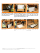
10.0 MECHANICAL INSTALLATION
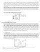
The module is considered to be in compliance with IEC 61730 and UL 1703 only when the module is mounted in the
manner specified by the mounting instructions below. We recommend using the following orientation to install the
module. Per UL certification standards, the maximum
number of modules connected in series/parallel for 60-
cell module is 19/1, for 72-cell module with maximum
system voltage of 1000V is 16/1 and 72-cell module with
maximum system voltage of 1500V is 24/1. However,
please refer to your local Authority Having Jurisdiction
(AHJ) as well as best installation practices for the
maximum number of modules that can be installed in
series and in parallel for your specific installation project
site and application.
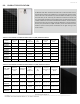
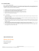
TABLE 9: SNOW & WIND LOAD AS SPECIFIED BY UL1703
*
Mounting Distance [mm]
Design Load for Front (Snow) [Pa]
**
Safety factor is 1.5
Design Load for Back (Wind) [Pa]
**
Safety factor is 1.5
A. 60-cell
297
3754
3754
B. 72-cell
370
3754
3754
*Mounting Distance – distance between edge of module and middle of clamp location.
This is assuming that modules are mounted on a certified railing system.
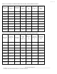
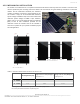
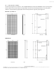
FIGURE 3: LANDSCAPE ORIENTATION
SEE A & B ON TABLE 9
FIGURE 4: PORTRAIT ORIENTATION
SEE A & B ON TABLE 9