
Installation Guide
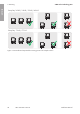
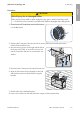
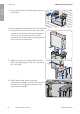
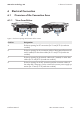
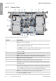
Table Of Contents
- Installation Manual
- Legal Provisions
- Table of Contents
- 1 Information on this Document
- 2 Safety
- 3 Scope of Delivery
- 4 Product Overview
- 5 Mounting
- 6 Electrical Connection
- 7 Commissioning
- 8 Disconnecting the Inverter from Voltage Sources
- 9 Decommissioning the Inverter
- 10 Technical Data
- 11 Compliance Information
- 12 Contact
- Instrucciones de instalación
- Disposiciones legales
- Índice
- 1 Indicaciones sobre este documento
- 2 Seguridad
- 3 Contenido de la entrega
- 4 Vista general del producto
- 5 Montaje
- 6 Conexión eléctrica
- 7 Puesta en marcha
- 8 Desconexión del inversor de la tensión
- 9 Puesta fuera de servicio del inversor
- 10 Datos técnicos
- 11 Información de cumplimiento
- 12 Contacto
- Instructions d’installation
- Dispositions légales
- Table des matières
- 1 Remarques relatives à ce document
- 2 Sécurité
- 3 Contenu de la livraison
- 4 Vue d’ensemble des produits
- 5 Montage
- 6 Raccordement électrique
- 7 Mise en service
- 8 Mise hors tension de l’onduleur
- 9 Mise hors service de l’onduleur
- 10 Caractéristiques techniques
- 11 Informations sur le respect des spécifications
- 12 Contact

5 Mounting
SMA Solar Technology AG
Installation ManualSBxx-1SP-US-41-IA-xx-1028
9. Secure the Conection Unit horizontally using screws
and washers.
10. Check whether the Connection Unit is firmly positioned.
11. Plug the Power Unit into the Connection Unit. Make
sure that the screw holes on the left and right sides
of the PowerUnit are directly over those of the
ConnectionUnit; and the cables protruding from the
PowerUnit must not be pinched.
12. Tighten two screws on the right and left side of the
PowerUnit (TX25) (torque: 6Nm ± 0.3 Nm (53in-
lb ± 2.65in-lb)).
13. Pull the ribbon cable used to connect the
communication assembly to the PowerUnit into the
ConnectionUnit, and plug it into the jack on the
communication assembly.
COM
SPS
AC-out
D-IN
SPS
A B
M1
X1 X2
M2
ANT.
FCC ID: SVF-KP20
IC: 9440A-KP20
ENGLISH