
Installation Guide
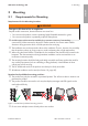
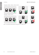
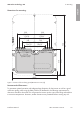
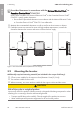
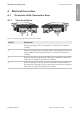
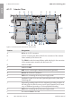
Table Of Contents
- Installation Manual
- Legal Provisions
- Table of Contents
- 1 Information on this Document
- 2 Safety
- 3 Scope of Delivery
- 4 Product Overview
- 5 Mounting
- 6 Electrical Connection
- 7 Commissioning
- 8 Disconnecting the Inverter from Voltage Sources
- 9 Decommissioning the Inverter
- 10 Technical Data
- 11 Compliance Information
- 12 Contact
- Instrucciones de instalación
- Disposiciones legales
- Índice
- 1 Indicaciones sobre este documento
- 2 Seguridad
- 3 Contenido de la entrega
- 4 Vista general del producto
- 5 Montaje
- 6 Conexión eléctrica
- 7 Puesta en marcha
- 8 Desconexión del inversor de la tensión
- 9 Puesta fuera de servicio del inversor
- 10 Datos técnicos
- 11 Información de cumplimiento
- 12 Contacto
- Instructions d’installation
- Dispositions légales
- Table des matières
- 1 Remarques relatives à ce document
- 2 Sécurité
- 3 Contenu de la livraison
- 4 Vue d’ensemble des produits
- 5 Montage
- 6 Raccordement électrique
- 7 Mise en service
- 8 Mise hors tension de l’onduleur
- 9 Mise hors service de l’onduleur
- 10 Caractéristiques techniques
- 11 Informations sur le respect des spécifications
- 12 Contact

5 Mounting
SMA Solar Technology AG
Installation Manual SBxx-1SP-US-41-IA-xx-10 25
Dimensions for mounting:
126.75
(4.99)
126.75
(4.99)
153
(6.02)
153
(6.02)
1 579.2
(7.06)
179.25
(7.06)
203
(7.99)
203
(7.99)
535
(21.06)
310
(12.2)
9 x 16
(0,34 x 0,63)
730
(28.74)
Figure 5 : Position of the anchoring points(Dimensions in mm (in))
Recommended Clearances:
To guarantee optimal operation and adequate heat dissipation for the inverter as well as a good
connection quality when using the SMACellularLTEModemKit, the following requirements for
clearances should be observed. This will prevent the inverter power output from being reduced due
to excessive temperatures. However, smaller clearances are permitted without causing any risk.
ENGLISH