
Installation Guide
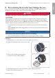
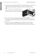
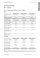
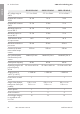
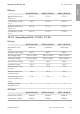
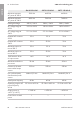
Table Of Contents
- Installation Manual
- Legal Provisions
- Table of Contents
- 1 Information on this Document
- 2 Safety
- 3 Scope of Delivery
- 4 Product Overview
- 5 Mounting
- 6 Electrical Connection
- 7 Commissioning
- 8 Disconnecting the Inverter from Voltage Sources
- 9 Decommissioning the Inverter
- 10 Technical Data
- 11 Compliance Information
- 12 Contact
- Instrucciones de instalación
- Disposiciones legales
- Índice
- 1 Indicaciones sobre este documento
- 2 Seguridad
- 3 Contenido de la entrega
- 4 Vista general del producto
- 5 Montaje
- 6 Conexión eléctrica
- 7 Puesta en marcha
- 8 Desconexión del inversor de la tensión
- 9 Puesta fuera de servicio del inversor
- 10 Datos técnicos
- 11 Información de cumplimiento
- 12 Contacto
- Instructions d’installation
- Dispositions légales
- Table des matières
- 1 Remarques relatives à ce document
- 2 Sécurité
- 3 Contenu de la livraison
- 4 Vue d’ensemble des produits
- 5 Montage
- 6 Raccordement électrique
- 7 Mise en service
- 8 Mise hors tension de l’onduleur
- 9 Mise hors service de l’onduleur
- 10 Caractéristiques techniques
- 11 Informations sur le respect des spécifications
- 12 Contact

8 Disconnecting the Inverter from Voltage Sources
SMA Solar Technology AG
Installation ManualSBxx-1SP-US-41-IA-xx-1062
6. Unscrew all six screws of the enclosure lid of the Connection Unit and remove the enclosure lid
carefully towards the front (TX25). When doing so, note that the LED assembly in the
enclosure lid and the communication assembly in the inverter are connected via a ribbon
cable.
7. Pull the ribbon cable connecting the LED assembly in
the enclosure lid to the communication assembly out
of the jack located on the communication assembly.
8. Use a current clamp to ensure that no current is present in the DC conductors.
9. Ensure there is no voltage on the AC-out terminal block between L1 and N and L2 and N
using a suitable measuring device. To do this, stick the test probe in each rectangular opening
of the terminal.
10. Ensure there is no voltage on the AC-out terminal block between L1 and the equipment
grounding conductor and L2 and the equipment grounding conductor using a suitable
measuring device. To do this, stick the test probe in each rectangular opening of the terminal.
ENGLISH