
Installation Guide


6 Electrical Connection
SMA Solar Technology AG
Installation ManualSBxx-1SP-US-40-IA-xx-1530
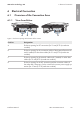
6.1.2 Interior View
COM
DC-in
SPS
AC-out
D-IN
SPS
A B
M1
X1 X2
M2
ANT.
FCC ID: SVF-KP20
IC: 9440A-KP20
Max. 30V DC
DISPLAY
BAT MFR
USB
A
B
C
D F
G
O H
J
P
K
L
M
N
I
E
Q
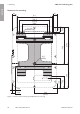
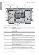
Figure 8 : Connection areas in the interior of the inverter
Position Designation
A
DC-in slot for DC connection
B
Module slot M1
C
Module slot M2
D
ANT. slot for connecting the Antenna Extension Kit (optional)
E
AC-out slot for the AC connection
F
SPS slot for connecting the secure power supply outlet
G Installation location for accessories (optional) approved by SMA Solar
Technology AG
H Equipment grounding terminal for the equipment grounding conductor of
the utility grid, the outlet for secure power supply operation and, if neces-
sary, an additional grounding or for the equipotential bonding
I
SPS slot for connecting the secure power supply switch
J
Pin connector D-IN is not used
K
Network ports A and B for connecting a router or network switch
L
USB port for connecting a USB flash drive (for service purposes)
M
MFR slot for connection to the multifunction relay
ENGLISH