
Installation Guide
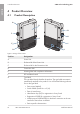

4 Product Overview
SMA Solar Technology AG
Installation ManualSBxx-1SP-US-40-IA-xx-1518
SMA Sensor Module
The SMA Sensor Module has different interfaces for connecting various sensors (i.e. temperature
sensor, irradiation sensor, anemometer or energy meter). The SMA Sensor Module converts the
signals of the connected sensors and transmits them to the inverter. The SMA Sensor Module can
be retrofitted.
SMA Cellular LTE Modem Kit
The inverter can be retrofitted with the SMA Cellular LTE Modem Kit.
The SMACellular LTE Modem Kit allows the direct data transmission between the inverter and the
internet portal SunnyPortal via the cellular network as an alternative to data transmission via
Ethernet or WLAN. In addition, the SMA Cellular LTE Modem Kit enables the communication
between the inverter and the energy meter.
The SMACellular LTE Modem Kit transmits up to four times a day a limited amount of data to
SunnyPortal. The standard term of the mobile data plan for the SMACellular LTE Modem Kit is five
years. All costs are covered within the term. No additional costs will be incurred. You have the
possibility to extend the term of the mobile data plan. For this purpose, contact SMA Solar
Technology AG. By using the SMACellular LTE Modem Kits, a local network connection is not
absolutely necessary. However, it is recommended to be able to view all information regarding the
system in SunnyPortal.
Energy meters in accordance with ANSI C12.20
The inverter can be retrofitted with the SMA Revenue Grade Meter Kit that in accordance with
ANSI C12.20 includes an energy meter.
The energy meter fulfills the accuracy class 0.5 in accordance with ANSI C12.20. The energy
meter is a so called PV production meter intended to measure the generated energy of the inverter.
The measured values of the energy meter can be used for billing purposes.
Grid Management Services
The inverter is a grid support interactive inverter.
The inverter was tested in accordance with the UL1741 SA (2016-09-07) to be compliant with the
source requirements documents of the states available at the time. For connecting the inverter to the
utility grid, no additional grid monitoring equipment is necessary. A description of the tested
functions and instructions on the activation and setting of functions can be found in the technical
information "Grid Support Utility Interactive Inverters" at www.SMA-Solar.com.
PVRapidShutdownSystemEquipment
The inverter is a PVRapidShutdownSystemEquipment and performs the function of voltage
reduction according to UL 1741 CRD PV Rapid Shutdown Systems 2015. When a rapid shutdown
is triggered by disconnecting the utility grid, the inverter discharges independently on the AC side to
≤30 V within 30 seconds.
If a disconnection device is used in addition between the inverter and the PV array that disconnects
the PV array in the case of a rapid shutdown, the inverter discharges independently on the DC side
to ≤30V within 30 seconds.
The electric discharge on the DC side is deactivated by default and must be activated manually
after commissioning of the inverter via the user interface.
ENGLISH