
Installation Guide
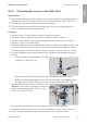
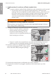
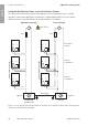
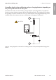
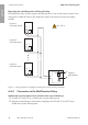
Table Of Contents
- Installation Manual
- Legal Provisions
- Table of Contents
- 1 Information on this Document
- 2 Safety
- 3 Scope of Delivery
- 4 Product Overview
- 5 Mounting
- 6 Electrical Connection
- 7 Commissioning
- 8 Disconnecting the Inverter from Voltage Sources
- 9 Decommissioning the Inverter
- 10 Technical Data
- 11 Compliance Information
- 12 Contact
- Instrucciones de instalación
- Disposiciones legales
- Índice
- 1 Indicaciones sobre este documento
- 2 Seguridad
- 3 Contenido de la entrega
- 4 Vista general del producto
- 5 Montaje
- 6 Conexión eléctrica
- 7 Puesta en marcha
- 8 Desconexión del inversor de la tensión
- 9 Puesta fuera de servicio del inversor
- 10 Datos técnicos
- 11 Información de cumplimiento
- 12 Contacto
- Instructions d’installation
- Dispositions légales
- Table des matières
- 1 Remarques relatives à ce document
- 2 Sécurité
- 3 Contenu de la livraison
- 4 Vue d’ensemble des produits
- 5 Montage
- 6 Raccordement électrique
- 7 Mise en service
- 8 Mise hors tension de l’onduleur
- 9 Mise hors service de l’onduleur
- 10 Caractéristiques techniques
- 11 Informations sur le respect des spécifications
- 12 Contact

6 Electrical Connection
SMA Solar Technology AG
Installation ManualSBxx-1SP-US-41-IA-xx-1038
Using the Multifunction Relay as a Fault Indicator Contact
You can use the multifunction relay as a fault indicator contact and have an error or smooth
operation of the inverter displayed or signaled via a suitable display device. You can connect
multiple inverters to one fault indicator or operation indicator, as needed.
B F
1
2
3
B F
1
2
3
B F
1
2
3
B F
1
2
3
B F
1
2
3
B F
1
2
3
= =
Light on
Grounding,
if applicable
Trouble-free
operation (B)
Error (F)
Operation message
Error message
Fuse
Light on
Error in the
inverter
Inverter
in operation
Inverter
in operation
Fuse
max. 30 V
DC
Figure 9 : Circuit diagram with multiple inverters for connection to an operation indicator and circuit diagram for
connection to a fault indicator (example)
ENGLISH