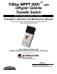
TM TriStar MPPT 600V Off-grid / Grid-tie Transfer Switch with Solar Charging System Controller Installation, Operation and Maintenance Manual For the most recent manual revisions, see the version at: www.morningstarcorp.com Solar Battery Charger with TrakStarTM Maximum Power Point Tracking Technology www.morningstarcorp.
Dimensions in inches [millimeters] TABLE OF CONTENTS 1.0 Important Safety Instructions 2.0 Getting Started 1.30 [ 33 ] 2.02 [ 51 ] 1.30 [ 33 ] 2.02 [ 51 ] 3.1 3.2 3.3 3.4 1.04 [ 26 ] 1.15 [ 29 ] 6.80 [ 173 ] .90 [ 23 ] .90 [ 23 ] 12.80 [ 325 ] 14.17 [ 360 ] 3.30 [ 84 ] 14.17 [ 360 ] 12.80 [ 325 ] 1.00 [ 25 ] 12 PLACES O 0.21 [ 5 ] 3.06 [ 78 ] 1.04 [ 26 ] 1.30 [ 33 ] 1.35 [ 34 ] 2.83 [ 72 ] .78 [ 20 ] 3.83 [ 97 ] 4.83 [ 123 ] 5.83 [ 148 ] 7.35 [ 187 ] 2.82 3.34 [ 72 ] [ 85 ] 1.
1.0 Important Safety Instructions SAVE THESE INSTRUCTIONS. This manual contains important safety, installation and operating instructions for the TS-MPPT-600V-TR solar controller. The following symbols are used throughout this manual to indicate potentially dangerous conditions or mark important safety instructions: ! ! WARNING: Indicates a potentially dangerous condition. Use extreme caution when performing this task.
• This charge controller is to be connected to DC circuits only. These DC connections are identified by the symbol below: • Ce contrôleur de charge ne doit être connecté qu’à des circuits en courant continu. Ces connexions CC sont identifiées par le symbole ci-dessous: Direct Current Symbol The TS-MPPT-600V-TR controller must be installed by a qualified technician in accordance with the electrical regulations of the country where the product is installed.
• Servicing of batteries should be performed, or supervised, by personnel knowledgeable about batteries, and the proper safety precautions. • Be very careful when working with large lead-acid batteries. Wear eye protection and have fresh water available in case there is contact with the battery acid. • Remove watches, rings, jewelry and other metal objects before working with batteries.
2.0 Getting Started The TS-MPPT-600V-TR with TrakStarTM MPPT Technology is an advanced maximum power point tracking solar battery charger. The controller features a smart tracking algorithm that finds and maintains operation at the solar array peak power point, maximizing energy harvest. 2.1 Overview Thank you for selecting the TS-MPPT-600V-TR solar charge controller. Both models are specialized components designed for use in grid-tie / off-grid systems.
NOTE: This equipment has been tested and found to comply with the limits for a Class B digital device, pursuant to Part 15 of the FCC rules. These limits are designed to provide reasonable protection against harmful interference in a residential installation. This equipment generates, uses, and can radiate radio frequency energy and, if not installed and used in accordance with the instruction manual, may cause harmful interference to radio communication.
2.4 Features TS-MPPT-60-600V-48-DB-TR Box The features of the TS-MPPT-600V-TR-GFPD model are shown below in Figure 2-1. An explanation of each feature follows.
Meter Hub (HUB-1) 19 - Solar Terminal Bridge (yellow) Isolates high voltage PV wiring from low voltage wiring area 20 - (+) and (-) Solar Power Terminals (pre-wired) (+) and (-) solar terminal connection points A Morningstar MeterBusTM network with multiple controllers requires a Meter Hub for electrical isolation. The HUB-1 allows communication between MeterBusTM compatible Morningstar products, including the TS-MPPT-600V-TR controller. DIN rail compatible. See section 5.2 for more details.
3.0 Installation Recommended Tools: • • • • 3.1 General Information WARNING: Equipment Damage or Risk of Explosion Never install the TS-MPPT-600V-TR in an enclosure with vented/flooded batteries. Battery fumes are flammable and will corrode and destroy the TS-MPPT-600V-TR circuits. ! CAUTION: Equipment Damage When installing the TS-MPPT-600V-TR in an enclosure, ensure sufficient ventilation. Installation in a sealed enclosure will lead to over-heating and a decreased product lifetime.
High and Low Voltage Wiring Positions - TS-MPPT-600V-TR 3.3 Conduit Knock-Outs and Wire Routing Knock-outs are provided for routing cables through conduit or wire glands. Table 3-1 details the knockout sizes and quantity provided on the TS-MPPT-600V-TR wiring box. Knockout placement dimensions are on the inside front cover. Figures 3-2 and 3-3 show knock-out types. The TS-MPPT-600V-TR wiring box provides continuous and separate paths for high voltage (solar) and low voltage (battery & COM) wiring routing.
3.4 Controller Installation Step 1 - Remove the Wiring Box Cover 3 ! 1 ! 4 CAUTION: Shock Hazard Disconnect all power sources to the controller before removing the wiring box cover. Never remove the cover when voltage exists on any of the TS-MPPT-600V-TR power connections. PRUDENCE : Risque de décharge électrique Déconnectez toutes les sources d’alimentation du contrôleur avant d’enlever le couvercle du boîtier de câblage.
Step 4 - Mounting to a Vertical Surface 1 The mounting location is important to the performance and operating life of the controller. The environment must be dry and protected from water ingress. If required, the controller may be installed in a ventilated enclosure with sufficient air flow. Never install the TS-MPPT-600V-TR in a sealed enclosure. The controller may be mounted in an enclosure with sealed batteries, but never with vented/flooded batteries.
Step 5 - Network Connections Network connections allow the TS-MPPT-600V-TR to communicate with other controllers or computers. A network can be as simple as one controller and one PC, or as complex as dozens of controllers monitored via the internet. Review section 5.0 for more information about networking and the connection(s) required for your system. WARNING: Shock Hazard Only route network cables in the same conduit as the photovoltaic power conductors if all conductors are rated for 600V.
Wire Size The four large power terminals are sized for 14 - 2 AWG (2.5 - 33.6 mm2) wire.* The terminals are rated for copper and aluminum conductors.** Use only UL-listed Class B 300 Volt stranded wire for battery connections. Good system design generally requires large conductor wires for the solar and battery connections that limit voltage drop losses to 2% or less.
+ D - D D To Grid-tie Inverter Solar Input G To Grid-tie Inverter Solar Input + D A A 48 Volt Battery Termination + Solar Array Inputs E - B C + - Up to 2 Strings F Loose Leads for Termination at a GFPD, or cut to length, and connected at the Controller Solar +/- Terminals (Step G) Figure 3-10.
Connect the Power Wires WARNING: Shock Hazard The solar PV array can produce open-circuit voltages in excess of 500 Vdc when in sunlight. Verify that the solar input breaker or disconnect has been opened (disconnected) before installing the system wires. AVERTISSEMENT : Risque de décharge électrique Le réseau PV solaire peut produire des tensions de circuit ouvert supérieures à 500 V cc à la lumière du soleil.
AVERTISSEMENT: Risque d’incendie. Si non Capteur de température distant (RTS) est connecté, utilisez le MPPT ProStar moins de 3m (10 pi) de les batteries. Compensation de la température interne sera utilisée si la RTS n’est pas connecté. Utilisation de la RTS est fortement recommandé. 2 1 4 Secure Wiring Divider with screw ! CAUTION: The TS-MPPT-600V-TR will not temperature compensate charging parameters if the RTS is not used.
If a TriStar meter is installed, check the “TriStar Settings” to confirm the Voltage Sense and the RTS (if installed) are both present and detected by the controller. MSViewTM PC software can also be used to confirm the voltage sense is working correctly. Step 9 - Adjust Settings Switches Switch 1: Future Use Select the charging source that will be connected to the TS-MPPT-600V-TR.
! CAUTION: Risk of Tampering The Ethernet Security settings switch does not block write commands to devices bridged via EIA485. REMARQUE : Le réglage des paramètres de réseau et des points de consignes personnalisés est toujours activé par les connexions RS-232 et EIA-485. Le contacteur de sécurité Ethernet n’active/ désactive que la configuration à distance par TCP/IP.
4.0 Operation Step 11 - Power-Up WARNING: Risk of Damage Connecting the solar array to the battery terminal will permanently damage the TS-MPPT-600V-TR. WARNING: Risk of Damage Connecting the solar array or battery connection with reverse polarity will permanently damage the TS-MPPT-600V-TR. AVERTISSEMENT: Risque d’endommagement La connexion du réseau solaire sur la borne de la batterie endommagera le TS-MPPT-600V-TR de façon permanente.
4.3 Battery Charging MPPT Technology The TS-MPPT-600V-TR utilizes Morningstar’s TrakStarTM Maximum Power Point Tracking (MPPT) technology to extract maximum power from high voltage solar arrays commonly used in grid-tie applications. The tracking algorithm is fully automatic and does not require user adjustment. TrakStarTM technology tracks an array’s maximum power point as it varies with weather conditions, ensuring that maximum power is harvested throughout the course of the day.
Float Stage After the battery is fully charged in the Absorption stage, the TS-MPPT-600V-TR reduces the battery voltage to the Float voltage set-point. When the battery is fully recharged, there can be no more chemical reactions and all the charging current is turned into heat and gassing. The float stage provides a very low rate of maintenance charging while reducing the heating and gassing of a fully charged battery. The purpose of float is to protect the battery from long-term overcharge.
Battery Charging Settings Preparation for Equalization First, confirm that all of the system loads are rated for the equalization voltage. Consider that at 0°C (32°F) the equalization voltage will reach 67.00 Volts for L-16 batteries with a temperature sensor installed. Disconnect any loads at risk of damage due to the high input voltage. The details of the TS-MPPT-600V-TR battery charging settings are shown in tables 4-1 and 4-2 below. All voltage settings listed are for nominal 48 Volt battery banks.
Absorption Extension Float Cancel Voltage Extended Absorption Absorption Bulk Float Absorption Bulk Float cancelled this charge cycle 50.00 V 49.20 V Absorption Extension Voltage time (hrs) time (hrs) 1:00 2:00 3:00 4:00 5:00 Float Cancel Voltage 1:00 6:00 Figure 4-3. Absorption extension charging profile. Float Time-Out Absorption Float Bulk 3:00 4:00 5:00 6:00 Figure 4-5. Float cancelled charging profile If battery voltage discharges below 50.
4.5 Push-button Temperature Compensation All charging settings are based on 25°C (77°F). If the battery temperature varies by 5°C, the charging setting will change by 0.60 Volts for a 48 Volt battery. This is a substantial change in the charging of the battery, and the use of the Remote Temperature Sensor (RTS) is recommended to adjust charging to the actual battery temperature.
4.6 LED Indications & Audible Warnings Valuable information is provided by the three LEDs visible through the front cover. Although there are many different LED indications, they have similar patterns to make it easier to interpret each LED display. Consider as three groups of indications: General Transitions // Battery Status // Faults & Alarms.
4.7 Protections, Faults & Alarms The TS-MPPT-600V-TR protections and automatic recovery are important features that ensure the safe operation of the system. Additionally, the TS-MPPT-600V-TR features real-time self diagnostics that report Fault and Alarm conditions as they occur. Faults are events or conditions that require the TS-MPPT-600V-TR to cease operation. A Fault usually occurs when a limit such as voltage, current, or temperature has been surpassed.
Alarms 5.0 Networking and Communication High Temperature Current Limit The TS-MPPT-600V-TR will limit the solar input current if the heatsink temperature exceeds safe limits. Solar charge current will be tapered back (to 0 amps if needed) to reduce the heatsink temperature. The TS-MPPT-600V-TR is designed to operate at full rated current at the maximum ambient temperature. This alarm indicates that there is insufficient airflow and that the heatsink temperature is approaching unsafe limits.
5.2 Morningstar MeterBusTM Morningstar’s proprietary MeterBusTM protocol allows communication between compatible Morningstar products. Use a MeterBusTM network to: • display select net system data for multiple TriStar / TriStar MPPT / TS-MPPT-600V-TR systems** • communicate with a TriStar Meter 2 -600V, a TriStar Meter 2 or TriStar Remote Meter 2 • communicate with a Relay Driver or other compatible Morningstar accessories (see section 2.
Serial Port Settings Adjust the serial port settings as follows: • 9600 BAUD • 8 data bits • 1 or 2 stop bits • no parity The serial RS-232 connection provides a direct connection between a TS-MPPT-600V-TR and a PC (or other serial device). Firmware updates can only be programmed through the RS-232 connection. The serial connection is not typically used for multi-controller networking. However, networking is possible using a USB hub and USB-Serial cables.
5.5 Ethernet ! CAUTION: Risk of Tampering The TS-MPPT-600V does not feature built-in network security. It is the responsibility of the user or network administrator to place the TS-MPPT-600V-TR behind a network firewall to prevent unauthorized access. ! PRUDENCE : Risque de tentative d’altération Le TS-MPPT-600V ne comporte pas de sécurité réseau intégrée.
Custom Settings SNMP The TriStar MPPT Setup Wizard in MSViewTM provides an interface to adjust all operating parameters. Morningstar’s MSViewTM PC software can connect to any TS-MPPT-600V-TR on the Ethernet network or through a RS-232 serial connection. Refer to the help documentation included with MSViewTM for more information.
6.0 Testing and Troubleshooting WARNING: RISK OF ELECTRICAL SHOCK. NO POWER OR ACCESSORY TERMINALS ARE ELECTRICALLY ISOLATED FROM DC INPUT, AND MAY BE ENERGIZED WITH HAZARDOUS SOLAR VOLTAGE. UNDER CERTAIN FAULT CONDITIONS, BATTERY COULD BECOME OVER-CHARGED. TEST BETWEEN ALL TERMINALS AND GROUND BEFORE TOUCHING. AVERTISSEMENT: RISQUE DE CHOC ÉLETRIQUE. NON ALIMENTATION OU AUX BORNES D’ACCESSOIRES SONT ISOLÉS ÉLECTRIQUEMENT DE L’ENTRÉE DE C.C ET DOIT ÊTRE ALIMENTÉS À UNE TENSION DANGEREUSE SOLAIRE.
Problem: Cannot connect to the controller via Ethernet Solution: See the Morningstar Product Connectivity Manual, available on our website: http://www.morningstarcorp.com/wp-content/uploads/2014/02/MS-Comm-Document-2010.pdf 7.0 Maintenance and Service Your TS-MPPT-600V-TR will provide years of reliable and trouble-free service. The unit contains no electromechanical parts such as relays or cooling fans that can wear out and fail. Additionally, there are no user-serviceable parts inside the controller. 7.
WARNING: Shock Hazard Disconnect all power sources to the controller before removing the wiring box cover. Never remove the cover when voltage exists on the TS-MPPT-600V-TR power connections. • External solar and battery disconnects are required. • Disconnect all sources of power to the controller before installing or adjusting the TS-MPPT-600V-TR. • There are no fuses or disconnects inside the TS-MPPT-600V-TR Do not attempt to repair.
• • • • Évitez le port de bijoux pendant l’installation. Le groupe de batteries doit être constitué de batteries du même type, fabricant et âge. Ne fumez pas à proximité du groupe de batteries. Les connexions d’alimentation doivent rester serrées pour éviter une surchauffe excessive d’une connexion desserrée. • Utilisez des conducteurs et des coupe-circuits de dimensions adaptées.
7.2 Maintenance Schedule • Porter des bottes et des gants de caoutchouc • Utiliser des outils avec poignées isolantes et évitez de placer des outils ou des objets métalliques sur le dessus de batteries. • Débrancher la source de charge avant de brancher ou dis-reliant les bornes de la batterie. • Utilisez des outils isolés et évitez de placer des objets métalliques dans la zone de travail. • Déterminer si batterie repose par inadvertance. Dans l’affirmative, supprimer la source du contact avec le sol.
MORNINGSTAR TECHNICAL SUPPORT POLICIES 8.0 Warranty and Policies Morningstar’s Technical Support Group is dedicated to providing unparalleled customer support. LIMITED WARRANTY Morningstar Solar Controllers and Inverters MS Support Scope: The TS-MPPT-60-600V-48-DB-TR and TS-MPPT-60-600V-48-DB-TR-GFPD controllers, are warrantied to be free from defects in material and workmanship for a period of FIVE (5) years from the date of shipment to the original end user.
WARRANTY CLAIM PROCEDURE 1. Before proceeding, please refer to product manual, including Troubleshooting section. 2. Contacting your authorized Morningstar distributor or dealer from whom you purchased the unit is the first step in the warranty process. Local dealers can often address warranty issues quickly. 3. If supplier is unable to address the issue, please contact Morningstar by e-mail (support@morningstarcorp.com) with: (A) purchase location -- business or company name 9.
Battery Charging Status LEDs #10 Battery Terminal Block Screws: LED Indication Green Flashing (fast) - 2 to 3 times per second Green Flashing - 1/2 sec on, 1/2 sec off Green Flashing (slow) - 1 sec on, 1 sec off Green Green & Yellow Yellow Yellow & Red Red Battery Charging Status Equalize charging stage Absorption charging stage Float charging stage 53.2 Volts ≤ Vbattery 52.0 Volts ≤ Vbattery < 53.2 Volts 50.8 Volts ≤ Vbattery < 52.0 Volts 48.0 Volts ≤ Vbattery < 50.8 Volts Vbattery < 48.
De-ratings Output Power vs. Array Input Voltage 60 Amp Battery Current Limit Battery Current vs. Array Voltage 425 Array Voltage (Volts) 525 Vb = 50 V 2500 60 Amp Battery Current Limit RRE NT L IMIT Vb = 40 V 60 Amp Battery Current Limit INPU T CU 2000 Vb = 30 V 15A POWER (Watts) Battery Current (Amps) 200 60 Amp Battery Current Limit 3000 OVER-VOLTAGE RANGE OVER-VOLTAGE 60 0 Vb = 60 V 3500 1500 60 Amp Battery Current Limit 600 Vb = 20 V 1000 Figure 9-1. Battery Current vs.
10.0 Appendix Efficiency 2% Voltage Drop Charts for 75°C Stranded Copper Wire 200 Vmp, 52 Vbatt 1-Way Wire Distance (feet), 48 Volt System 96 94 60 Amps 25 Amps 20 Amps 15 Amps 89.6 97.8 107.5 119.5 134.4 153.6 179.2 215.1 0 71.0 77.5 85.2 94.7 106.6 121.8 142.1 170.5 2 44.7 48.7 53.6 59.6 67.0 76.6 89.3 107.2 4 28.1 30.7 33.8 37.5 42.2 48.2 56.3 67.5 6 17.7 19.3 21.2 23.5 26.5 30.3 35.3 42.4 8 11.1 12.2 13.4 14.9 16.7 19.1 22.3 26.7 10 7.0 7.6 8.4 9.3 10.5 12.0 14.0 16.8 12 4.4 4.8 5.3 5.8 6.6 7.
2% Voltage Drop Charts for 75°C Solid Copper Wire 2% Voltage Drop Charts for 90° Stranded Copper Wire 1-Way Wire Distance (feet), 48 Volt System 60 Amps 55 Amps 50 Amps 45 Amps 40 Amps 35 Amps 30 Amps 1-Way Wire Distance (feet), 48 Volt System 25 Amps 20 Amps 15 Amps 111.2 121.3 133.5 148.3 166.8 190.6 222.4 266.9 0 88.2 96.2 105.8 117.6 132.3 151.2 176.4 211.7 2 55.4 60.5 66.5 73.9 83.2 95.1 110.9 133.1 4 34.9 38.0 41.9 46.5 52.3 59.8 69.8 83.7 6 21.9 23.9 26.3 29.2 32.9 37.6 43.9 52.6 8 13.
2% Voltage Drop Charts for 90°C Solid Copper Wire This product contains the lightweight IP (lwIP) networking stack, which has been incorporated under the following license: 1-Way Wire Distance (feet), 48 Volt System 60 Amps 55 Amps 50 Amps 45 Amps 40 Amps 35 Amps 30 Amps 25 Amps 20 Amps 15 Amps 111.2 121.3 133.5 148.3 166.8 190.6 222.4 266.9 0 88.2 96.2 105.8 117.6 132.3 151.2 176.4 211.7 2 55.4 60.5 66.5 73.9 83.2 95.1 110.9 133.1 4 34.9 38.0 41.9 46.5 52.3 59.8 69.8 83.7 6 21.9 23.9 26.3 29.