
Installation Guide


Installation Guide
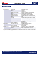
TROUBLESHOOTING
Problem Possible Cause Possible Solution
Panel (pair) voltage is 0V No mains supply
(LED OFF)
Check area utility operational
Check mains ON
Check mains fuse
FRS-ESW1 power supply failure
(LED OFF)
Check mains voltage between L & N marked terminals
Check 24VDC between + & - marked terminals
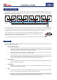
FRS-ESW1 switch activated Turn red actuator anti-clockwise to release button
No FRS-ESW1 switch output
(LED OFF)
Check 24VDC between switch out terminal & PSU – marked
terminal
Broken cable
(LED OFF)
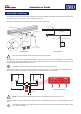
Check 24VDC between terminals of remote Tyco SuperSeal
connector (pin 1 +24VDC\pin 2 0VDC)
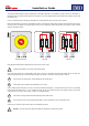
PV array not connected Check all PV to FRS-01 / FRS-02 input connections
Incorrect FRS-01 / FRS-02 polarity
connection
Check PV array Positive (+) goes to FRS-01 / FRS-02
Positive (+) and PV array Negative (-) goes to FRS-01 /
FRS-02 Negative (-)
No FRS-01 / FRS-02 output Replace FRS-01 / FRS-02
PV Inverter input 0V No DC isolator (if tted) input Check FRS-01 / FRS-02 output connections
Check DC inputs to isolator
DC Isolator (if tted) OFF Turn DC Isolator ON
String voltage too low Incorrect FRS-01 / FRS-02 polarity
connection
Check all PV array Positive (+) go to FRS-01 / FRS-02
Positive (+) and PV array Negative (-) go to FRS-01 /
FRS-02 Negative (-)
In the occurrence of a re IMO recommend that all elements of the FireRaptor Rapid Shutdown system be assessed for operational suitability by
a competent person prior to re-energising.
IMO Precision Controls Ltd. The Interchange, Frobisher Way, Hateld, Herts AL10 9TG UK
Tel: +44 (0)20 8452 6444 Fax: +44 (0)20 8450 2274
Information correct at time of print. Errors & omissions excepted.
www.imopc.com