
Installation Guide


i
The FireRaptor is OFF giving no array output until such time as the external DC power supply is energised and the Emergency Switch
is in its non-activated position.
Installation Guide
INSTALLATION & CONNECTION
One FireRaptor will control two solar panels and for compliance with 2017 NEC it should be mounted within the array boundary of the two panels,
where the two panels are no greater than 1’ (foot) /30cm apart from each other.
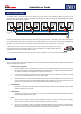
Determine the mounting location of the FireRaptor (FRS-01 / FRS-02) and x as shown below.
Do not drill though the FireRaptor as this will damage the unit and prevent operation.
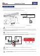
Mounting Method 1 offers ease of xing whilst Mounting Method 2 can be used where more effective use of the FireRaptor’s onboard temperature
sensing is required, by placing the FireRaptor in position against the underside of the PV panel (or the surface where the temperature needs to be
sensed). Once mounted ensure that the FireRaptor is secure.
n
The FireRaptor is housed in a plastic enclosure therefore grounding of the product is unnecessary.
Mounting Method 1 Mounting Method 2
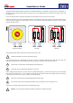
Connect the two PV panels in series (typical wiring example below). Connect the array Positive (+) output connector to the FireRaptor Positive (+)
input connector. Connect the array Negative (-) output connector to the FireRaptor Negative (-) input connector.
!
Warning – Ensure that you have identied the inputs correctly. The FireRaptor input cables are the shorter ones.
Connect the FireRaptor’s two output cables to the DC isolator/Solar Inverter ensuring that the correct polarity is maintained throughout the electrical
wiring.
Solar Panel
FireRaptor
Mounting Frame
FireRaptor
Mounting Frame
Bracket
Star Washer
Flat Washer
(¼” or M6
screws & washer)
String
Panels
PWR
In Out
STG
+ -
PAN
+ -
FireRaptor
IMO
Power Panels String
FireRaptor External Wiring
7mm
14mm
Keyhole