
Installation Guide

PAGE 15 OF 18
MISSION SOLAR ENERGY LLC
ELECTRONIC versions are uncontrolled except when accessed directly from document control directory. Printed copies are uncontrolled unless verified against online document.
COPYRIGHT 2019 MISSION SOLAR ENERGY LLC, ALL RIGHTS RESERVED
REVISION:[ R10] 6/12/2019
RELEASE DATE: 11/16/2016
12.0 ELECTRICAL INSTALLATION
12.1 LOCAL / NATIONAL CODE AND
LOCAL REGULATION
To carry out installation, local regulations that may
apply should be taken into account such as NEC (USA)
or Canadian Electrical Code (Canada). Wiring should
be performed by a qualified and licensed
professional. Wiring should be protected to help
ensure personal safety and to prevent damage. All
modules connected in series should be of same model
number and/or same type. Do not connect modules
in parallel without using a combiner box or
equivalent.
Under normal conditions, a photovoltaic module is
likely to experience conditions that produce current
and/or voltage other than reported at standard test
conditions. The requirements of the National Electric
Code (NEC) in Article 690 shall be followed to address
these increased outputs. In installations not under
the requirements of the NEC, the values of ISC and
VOC marked on this module should be multiplied by
a factor of 1.25 when determining component
voltage ratings, conductor capacities, over current
device ratings and the size of controls connected to
the PV output.
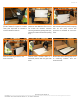
12.2 WIRING
Mission Solar PV modules come with a factory
assembled Junction Box. Do not open the junction
box in any case. Wiring must be done in accordance
with local/national code and regulations; wear
protective gloves and shoes to avoid electric shock.
Address the following recommendations:
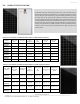
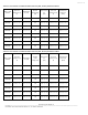
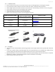
• The modules combined in parallel will produce a
specific current output. Each series string or
module is required to be fused. Table 1 describes
the maximum fuse size allowed.
• Do not connect the modules if the connectors are
wet.
• Be sure to put the cables away from sharp edges.
• If you need additional cables, you must use
exclusively solar cable of 12AWG/4mm2
minimum cross-sections, with ability to work in a
temperature range of at least -40
o
C and 90
o
C.
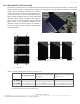
• Install the modules so that water from rain or
condensation cannot penetrate inside the cable
conduits.
• Fix cables to the structure so that the connectors
are protected from water ingress. Cables should
be held by UV resistant clamps or ties.
• To minimize possible effects of lightning induced
voltages, the surface of all conductive loops must
be as small as possible.
• Check that the wiring is correct before starting
the installation by verifying that the open voltage
is within expected values.
• Protect cables that could suffer mechanical
damage.
• Avoid direct sunlight on cables.
• Maximum series fuse rating 20A.
• Details for wiring in accordance with the NEC, and
that the grounding method of the frame of arrays
shall comply with the NEC, article 250.
• Installation shall be in accordance with CSA C22.1,
Safety Standard for Electrical Installations,
Canadian Electrical Code and Part 1.
• Modules may be connected in series (voltage
additive) and/or in parallel (current additive) to
produce the appropriate electrical output. When
connecting modules in parallel, each module (or
series string of modules so connected) shall be
connected according to the maximum series fuse
as specified.
• Recommended series connection of module open
circuit voltage should not exceed 80% limits range
of the system voltage and the fuse should be
connected at the end of each array.
• The installation instructions specify that
grounding is achieved through securement to the
array frame. The array frame must be grounded
in accordance with NEC Article 250.