
Installation Guide

PAGE 14 OF 18
MISSION SOLAR ENERGY LLC
ELECTRONIC versions are uncontrolled except when accessed directly from document control directory. Printed copies are uncontrolled unless verified against online document.
COPYRIGHT 2019 MISSION SOLAR ENERGY LLC, ALL RIGHTS RESERVED
REVISION:[ R10] 6/12/2019
RELEASE DATE: 11/16/2016
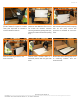
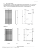
For Bolt fitting, Module shall be bolted to support structures through four mounting holes using M7*16mm bolts
together with flat washer, spring washer and nut. The applied torque should be 16±2 Nm. For Clamp fitting, once the
module is aligned and centered, fully tighten the screws in the end-clamps in place to 16±2 Nm. All the end clamps
should be torqued to this value. Ensure that the channel nuts do not extend outside of the purlin. Drop the mid-clamp
into the purlin.
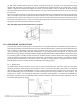
Place the channel nut inside purlin and place the grounding clip between the module and purlin with the grounding clip
tabs in the middle of the purlin. Install the final two end-clamps once the final module has been placed. Similar to the
End-Clamp section, place an end-clamp on each purlin, flush to the final module with the lip of the end-clamps on top of
the module. Fully tighten the end - clamps once they are properly placed. If the channel nuts extend outside of the purlin,
spacing has been done improperly and needs to be fixed.
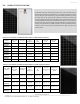
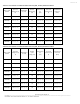
Note: Allowable clamp minimum dimensions are as follows:
11.0 GROUNDING INSTRUCTIONS
A module with exposed conductive parts is considered to be in compliance with UL 1703 and IEC 61730 only when it is
electrically grounded in accordance with the instructions presented below and the requirements of the National Electric
Code. To reduce the possibility of electrical shock, ground the frame of the module or array before wiring the circuit
using a grounding method that meets NEC requirements for grounding solar electrical systems. In order to install,
Mission Solar Energy modules shall be grounded using grounding hardware that has been certified to meet requirements
for grounding systems in UL467, UL1703 or UL1741 on anodized aluminum frames. Mission Solar Energy recommends
one of the following methods of grounding the module frame. The attachment must be made in conformance with the
grounding device manufacturer’s instructions and be used with a racking system in compliance with UL Outline
(Standard) 2703 where this module has been evaluated with that racking system.
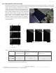
11.1 WEEB-UIR
The WEEB washer family of products can be used to bond anodized aluminum, galvanized steel, steel and other
electrically conductive metal structures. All installations shall be in accordance with NEC requirements in the USA and
with CSA C22.1 in Canada. The WEEB washers are for use with modules that have a maximum fuse rating of less than
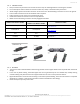
25A. Use WEEB-UIR to bond solar modules to module mounting purlin and torque fasteners to 7ft-lb / 9.5N-m, use
Penetrox-A on threads. The following UL Recognized component, Bonding Washer, manufactured by BURNDY LLC
(E351343) in combination with the following model number PV module(s), used with a flat washer (optional), a M5 size
nut and bolt (see Figure 6 for details).