MODULE INSTALLATION AND USER MANUAL - PERC AND MONO SERIES REV10 | 6/12/2019
PAGE 1 OF 18 T AB LE OF CO NT EN T S 1.0 DISCLAIMER ................................................................................ 3 2.0 HANDLING AND USE ..................................................................... 3 3.0 LIMITATION OF LIABILITY AND LIMITED REMEDIES ........................... 3 4.0 GENERAL INSTRUCTIONS ............................................................... 3 FIGURE 1: OVERVIEW OF MSE PERC / MONO 72-cell ...................................................................
PAGE 2 OF 18 12.0 ELECTRICAL INSTALLATION ........................................................... 15 12.1 12.2 12.3 12.4 Local / National Code and Local Regulation .......................................................................................... 15 Wiring .................................................................................................................................................... 15 Connectors ..............................................................................
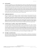
PAGE 3 OF 18 1.0 DISCLAIMER This manual is provided on an “as is” basis without warranty, covenant or representative of any kind, express or implied, including the warranties of merchantability or fitness for a particular purpose. Mission Solar Energy uses its best efforts to ensure the accuracy of the contents of this manual; however, Mission Solar Energy is not responsible for the accuracy of said contents or results of your use of the same.
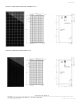
PAGE 4 OF 18 FIGURE 1: OVERVIEW OF MSE PERC / MONO 72-cell FIGURE 2: OVERVIEW OF MSE PERC 60-cell MISSION SOLAR ENERGY LLC ELECTRONIC versions are uncontrolled except when accessed directly from document control directory. Printed copies are uncontrolled unless verified against online document.
PAGE 5 OF 18 5.0 SAFETY 5.1 GENERAL WARNING You must understand and follow all applicable local, state and federal regulations in addition to standards for building construction, electrical design, fire and safety. Check with local authorities to determine applicable permitting requirements before attempting to install or maintain PV modules. • • • 5.2 • • • 5.3 • • • • WARNING Module interconnects pass direct current (DC) when exposed to sunlight or other light sources.
PAGE 6 OF 18 6.0 OPERATING CONDITIONS 6.1 TEMPERATURE All the modules must be mounted in environments that ensure they operate within the following maximum and minimum operating temperatures. • • 6.2 Maximum Operating Temperatures: +90oC (194oF) Minimum Operating Temperatures: -40oC (-40oF) INSTALLATION CONDITION Orient the module correctly. Mount the modules with the junction box in the uppermost position and hang the wires downwards to avoid the ingress of water.
PAGE 7 OF 18 7.0 UNPACKING & STORAGE 7.1 Always wear Proper PPE when handling MSE Panels GENERAL INSTRUCTIONS Store modules in an environment consistent with prudent solar industry practices, including, storage in dry conditions such that modules (or any part thereof) are not immersed in water. Do not carry the module above the head. Do not allow children or unauthorized persons near the installation site or storage area of modules. Do not drop or place objects such as tools on the modules.
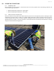
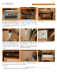
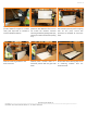
PAGE 8 OF 18 8.0 UNPACKING Always wear Proper PPE when handling MSE Panels Prior to unpacking, ensure pallet is set on a level surface and proper PPE is equipped by all personnel. Proper PPE for unpacking includes but is not limited to eye protection, cut-resistant gloves and steel-toe footwear. Cut the two green strips of banding Lift the pallet lid and set away from material with scissors. These strips are unpacking area. under high tension and will snap when cut.
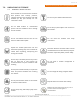
PAGE 9 OF 18 (Optional) If tape has been used to The first module must be separated and provide additional support to module pulled out with additional care so as to stack, peel tape back as needed to not scratch the modules. Continue remove individual modules. removing modules by peeling back tape, moving the module forward and pulling it up. Slide the remaining modules to the front of the box. When four modules remain, the stack will inherently become prone to tipping over.
PAGE 10 OF 18 9.0 PRODUCT SPECIFICATION PV Modules have been certified to IEC 61215 for a maximum static load on the back of the module of up to 2400 Pa (i.e. wind load) and a maximum static load on the front of the module of up to either 2400 Pa or 5400 Pa (i.e. wind and snow load). For UL 1703 only, PV modules are tested to a front side and rear side applied load based on 78 psf design load. The performance of solar modules is defined on the uniform standard test conditions.
PAGE 11 OF 18 TAB L E 3: E L EC TR IC A L R A TIN G S O F M S E P ER C 6 0 ( 5B B , B L A CK ) M O DU L E S ER I E S Model – P PERC Crystalline Open Circuit Voltage at STC, (V dc) Rated Voltage at STC, (V dc) Maximum System Voltage, (V dc) Rated Current at STC, (A dc) Short-Circuit Current at STC, (A dc) Rated Maximum Power at STC, (Watts) MSE285SQ8T 39.69 ± (0~+ 3%) 32.68 ± (0~+ 3%) 1000 8.720 ± (0~+ 3%) 9.367 ± (0~+ 3%) 285.00 ± (0~+3%) MSE290SQ8T 39.91 ± (0~+ 3%) 32.
PAGE 12 OF 18 10.0 MECHANICAL INSTALLATION The module is considered to be in compliance with IEC 61730 and UL 1703 only when the module is mounted in the manner specified by the mounting instructions below. We recommend using the following orientation to install the module.
PAGE 13 OF 18 10.1 MOUNTING CLAMPS Use the mounting holes as a reference - 297 mm (MSE PERC 60) or 370 mm (for MSE PERC 72) for mounting clamp location. Make sure that the module is evenly between the two rails and sits perpendicular on the railing. If the module is not perpendicular, slightly adjust the end-clamp positions to get the proper alignment.
PAGE 14 OF 18 For Bolt fitting, Module shall be bolted to support structures through four mounting holes using M7*16mm bolts together with flat washer, spring washer and nut. The applied torque should be 16±2 Nm. For Clamp fitting, once the module is aligned and centered, fully tighten the screws in the end-clamps in place to 16±2 Nm. All the end clamps should be torqued to this value. Ensure that the channel nuts do not extend outside of the purlin. Drop the mid-clamp into the purlin.
PAGE 15 OF 18 12.0 ELECTRICAL INSTALLATION • 12.1 LOCAL / NATIONAL CODE AND LOCAL REGULATION • • • To carry out installation, local regulations that may apply should be taken into account such as NEC (USA) or Canadian Electrical Code (Canada). Wiring should be performed by a qualified and licensed professional. Wiring should be protected to help ensure personal safety and to prevent damage. All modules connected in series should be of same model number and/or same type.
PAGE 16 OF 18 12.3 CONNECTORS • • • • • • • Keep connectors dry and clean. Ensure that connector caps are hand-tight before connecting the modules. Do not attempt to make an electrical connection with wet, soiled, or otherwise faulty connectors. Avoid sunlight exposure and water immersion of the connectors. Avoid allowing connectors to rest on the ground. Ensure cable connectors are UL and Canadian code complaint. Faulty connections can result in arcs and electrical shock.
PAGE 17 OF 18 13.0 MAINTENANCE 13.1 VISUAL INSPECTION Mission Solar Energy recommends that PV systems be periodically inspected by the installer or other qualified personnel. The purpose of the PV system inspection is to ensure that all system components are functioning properly. At a minimum, this inspection should confirm the following: • • • • • All cables and connector attachments are undamaged and properly secured. No sharp objects are in contact with the PV module surfaces.
PAGE 18 OF 18 MISSION SOLAR ENERGY LLC ELECTRONIC versions are uncontrolled except when accessed directly from document control directory. Printed copies are uncontrolled unless verified against online document.