Installation Guide Version 2.
Installation Guide DISCLAIMER No part of this publication may be stored, reproduced or copied without prior written permission from IMO Precision Controls Ltd. The material furnished in this document is believed to be accurate and reliable however, IMO Precision Controls Ltd assumes no responsibility for the use of this material. IMO Precision Controls Ltd reserves the right to make changes to the information contained at any time without prior notice.
Installation Guide SAFETY INSTRUCTIONS ! The FireRaptor is an electrical product and should only be installed by a suitably qualified person, in accordance with local regulations. ! When modifying and existing installation, isolate the inverter from the PV array by turning OFF the DC isolator / switch disconnect or turn OFF the inverter and the AC switch. ! PV Panel input and output connectors are not environmentally sealed until they are mated.
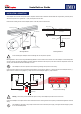
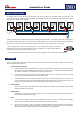
Installation Guide INSTALLATION & CONNECTION One FireRaptor will control two solar panels and for compliance with 2017 NEC it should be mounted within the array boundary of the two panels, where the two panels are no greater than 1’ (foot) /30cm apart from each other. Determine the mounting location of the FireRaptor (FRS-01 / FRS-02) and fix as shown below.
Installation Guide The Emergency Rapid Shutdown Switch Unit (FRS-ESW1 / FRS-ESW2 / FRS-ESW1-K / FRS-ESW2-K), hereafter referred to as FRS-ESW1, for installation; can be conveniently located anywhere for emergency access and is supplied with an internal 24VDC power supply to interface with the FireRaptor units. Locate a convenient position for mounting the FRS-ESW1 unit ensuring that mains power connection is also available.
Installation Guide MULTIPLE INSTALLATIONS One FireRaptor FRS-01 / FRS-02 will control two solar panels and by series connection of the FireRaptor, multiple solar panel pairs can be connected to form a greater capacity system. The diagram below illustrates a typical example of a FireRaptor protected 2kW installation using eight 250W solar panels and four FRS-01 FireRaptors.
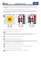
Installation Guide i The Emergency Shutdown Switch is a typical “one push” large red emergency push button which requires an anti-clockwise twist to release. n The FRS-ESW1 and FRS-ESW1-K includes an LED status indicator which when used with FRS-01 signifies 24VDC power status (ON) or power loss (OFF). n The FRS-ESW2 and FRS-ESW2-K includes an LED status indicator which when used with FRS-02 signifies 24VDC power status (ON), or power loss or trip (OFF).
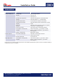
Installation Guide TROUBLESHOOTING Problem Possible Cause Possible Solution Panel (pair) voltage is 0V No mains supply (LED OFF) Check area utility operational Check mains ON Check mains fuse PV Inverter input 0V FRS-ESW1 power supply failure (LED OFF) Check mains voltage between L & N marked terminals FRS-ESW1 switch activated Turn red actuator anti-clockwise to release button No FRS-ESW1 switch output (LED OFF) Check 24VDC between switch out terminal & PSU – marked terminal Broken cable (LED