
Installation Guide


Page 7 of 10
EXD 8.5-001 PV Module User Manual_REV.02 Effective Date: July 8
th
, 2019
For Rooftop installation:
Ensure to comply with all local building codes.
Freestanding modules turn a Class B rooftop into a Class C rooftop.
Use appropriate corrosion-proof fastening materials.
Top or Bottom clamping methods will vary and are dependent on the mounting structures.
Follow mounting guidelines recommended by the PV racking Suppliers.
7.3.3 Electrical Installation
All wiring should be performed by registered installer and comply with local codes ®ulations.
The wiring must ensure that the loss of nominal voltage is less than 2%, it is recommended to maintain this loss
around 1% of the nominal power.
Heliene modules are provided with stranded copper cables – with exception of Class I Division 2 (CID2) products.
The maximum voltage of the system must be less than the maximum certified voltage, the maximum input voltage
of the inverter and the other electrical devices installed in the system. Heliene’s modules are rated from 600V ~
1500V, please check your specification sheet and ask your manufacturer for confirmation.
Under normal conditions, a photovoltaic module is likely to experience conditions that produce more current
and/or voltage than reported at standard test conditions. The requirements of the National Electrical Code (NEC)
in Article 690 shall be followed to address these increased outputs. In installations not under the requirements of
the NEC, the values of I
SC
and V
OC
marked on this module should be multiplied by a factor of 1.25 when
determining component voltage ratings, conductor ampacities, overcurrent device ratings, and size of controls
connected to the PV output.
For CID2 rated modules, glands and cables are not provided with the product, wiring methods shall be per the CEC,
NEC and/or applicable local codes. All cable fittings shall be suitable for hazardous locations and environmental
applications.
Wiring
PV modules that are connected in series should have similar current, and PV modules that are connected in
parallel should have similar voltage. The number of modules in series and in parallel shall be designed reasonable
according to the system configuration.
All Heliene modules contains installed bypass diodes, if the modules are incorrectly connected to each other this
will result in damage of bypass diodes, cables or junction boxes.
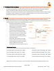
Class I Division 2 Field Wiring:
To connect the modules, remove the knockout plugs on the junction box and install ¾ inch cable glands fittings (torque
to 33 in-lb) suitable for hazardous locations and environmental applications. Wires can then be connected to the
positive and negative screw terminals. These terminals are identified by a positive and negative sticker. Make sure to
use the screw terminals that are not holding bypass diodes.
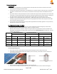
The recommended rating for wiring connections is 6 mm2 and never less than 4 mm2, 10 AWG recommended and
never less than 12 AWG. Only use cable listed by UL4703 PV wire, 90°C thermal insulated in accordance with all the
local fire, building and electrical codes.