
User Manual

L N
OUT
L N
GEN
L N
GRID
N
E
U
L1 L2
GRID
L1 L2
GEN
N
E
U
N
E
U
L1 L2
OUT
AC Subpanel
Loads
L1
L2
NEU
GROUND
L1
L2
NEU
GROUND
AC
Source
Neutral-Ground
Bond
AC Generator
AC Distribution Panel
N
Generator
Start
Battery Bank
Vented Battery Enclosure
Neutral
HOT L1
Ground
AC LEGEND
N
L1
Remove the On/Off jumper
to enable the use of switch
or Emergency Power Off
(EPO)
Ground
Electrode
Conductor
(Ground Rod)
RTS
Cable
On/Off Switch or EPO
RELAY
AUX
+ -
12V
AUX
Switch
INV
Remote
Battery
Temp
PV Array #1 PV Array #2
HOT L2
L2
EPO
N
L1
L2
Utility Grid
900-0176-01-00 REV A.vsd\Page 4\2015-04-29
©2014 OutBack Power Technologies. All Rights Reserved.
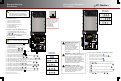
RTS
FPR-4048A wiring
FPR-8048A wiring
and external system
RELAY
AUX
+ -
12V
AUX
Switch
INV
Remote
Battery
Temp
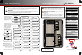
Wiring FP-Radian
IMPORTANT:
Example only. Actual wiring may vary depending
on system details and local electric code. Most factory
wiring is not shown.
Negative
PV
Positive
Ground
DC LEGEND
Battery
Positive
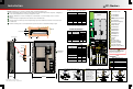
The FPR-4048A follows the same wiring
layout as the FPR-8048A with the following
exceptions (depicted):
o No DC positive (+) plate is present.
A single positive battery cable is used.
The positive cable lug connects to the
base of the main DC disconnect (with
the GFDI cable). See Positive
Battery Cable Connections on the
Installation page.
o A single battery negative (-) cable is
used. It connects to the far right shunt.
o A single PV positive cable (+) and bus
bar are used.
o A single PV negative (-) cable is used.
It connects to the far left shunt. See
Negative PV Cable Connections.
N
L2
L2
L2
L1
L1
L1
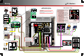
NOTE:
FM80 negative (-) is prewired.
PV negative (-) is installed at the
same location with a ring terminal.
(See Negative PV Cable
Connections.) It can also be
installed in the FM80 controller.
FM80(-) FM80(-)
O
I
O
I
O
I
O
I
O
I
O
I
O
I
O
I
O
I
O
I
O
I
O
I
PV Array #2
PV Array #1
PV(-) Battery(-)
PV(+)Battery(+)
L2
L1