
User Manual

Installation
900-0176-01-00 REV A.vsd\Page-2\2015-04-29
©2014 OutBack Power Technologies. All Rights Reserved.
FP-Radian
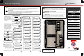
AC Wire Sizes and Torque Values
OutBack recommends that conductors be
#6 AWG THHN copper, or larger, rated to 75°C
(minimum) unless local code requires otherwise.
AWG In-lb
#14 to #10 20
#8 25
#6 to #4 35
#3 35
#2 40
#1 50
1/0 50
mm
2
2.5 to 6
10
16 to 25
35
35
50
70
Nm
2.3
2.8
4.0
4.0
4.5
5.6
5.6
Wire Size Torque
Torque Requirements
Minimum DC Cable based on
the DC Circuit Breaker
Torque
In-lb Nm
50 5.6
225 25.4
225 25.4
Circuit
Breaker
Cable Size
125 1/0 (70 mm
2
)
175 2/0 (70 mm
2
)
250 4/0 (120 mm
2
)
35 4.080 #4 AWG (25 mm
2
)
35 4.060 #6 AWG (16 mm
2
)
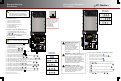
Positive Battery Cable Connections
CAUTION:
Equipment Damage
When connecting cables
from the FP-Radian
to the battery terminals,
make sure to observe
the proper polarity.
Connecting the cables
incorrectly can
damage or destroy the
equipment and void the
product warranty.
Negative Battery Cable
Connections
Green
> 90% (blinks if charge parameters
are met)
Color
Red
Yellow
Yellow
Yellow ≥ 80%
≥ 70%
≥ 60%
≥ 60% off, < 60% solid, < 50% blinks
Battery State of Charge
FN-DC LED Indicators
DC
Positive
(+) Plate
Flat
Washer
Lock
Washer
Flat
Washer
Flat
Washer
Battery
Negative
(–)
DC
Negative (-)
Plate
(GS-SBUS)
FPR-8048A FPR-4048A
DC Disconnect
Stud
Battery
Positive
(+)
FM80
Positive (+)
Flat
Washer
Nut
Lock
Washer
FN-DC
Positive
(+) Sense
4
22
!
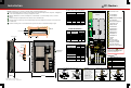
NOTE: Working gloves are strongly recommended when performing installation steps.
Ensure the mounting surface is strong enough to handle 3 times the total weight of all the components. Add plywood
or other reinforcing material as necessary to strengthen the surface.
Attach the wall bracket. Center the mounting holes on the wall studs. Use all 6 mounting screws to secure the
bracket.
Lift the inverter high enough that the inverter bracket is above the wall bracket.
Lower the inverter so that the top of the back plane flange slips into the wall bracket. Ensure the unit is centered on
the wall bracket.
Install the mounting screws. See illustration below for preferred locations for maximum mounting strength.
1
3
4
2
5
AC Circuit Breakers
1
Ground Fault Detector-Interrupter
(GFDI)
2
3
4
DC Terminals - Inverter
AC Terminals - Inverter
5
DC Circuit Breakers
6
PV Circuit Breakers
7
8
Mechanical Interlock (Bypass)
9
10
Communication Ports
Auxiliary Terminals
11
12
13
14
15
AC OUT Bus Bar L1
16
17
18
19
AC OUT Bus Bar L2
GRID IN Bus Bar L1
GRID IN Bus Bar L2
GEN IN Bus Bar L1
GEN IN Bus Bar L2
AC Neutral
Ground
20
DC Positive (+) Plate
(not used on FPR-4048A)
PV Negative (–) Terminals
21
PV Positive (+) Bus Bars
DC Negative (–) Plate (GS-SBUS)
Circuit Breaker
Stud
Torque
In-lb Nm
M8 20 2.3
¼ - 20 35 4.0
5/16 - 18 50 5.6
3/8 - 16 225 25.4
DC Plates
Torque
In-lb Nm
Upper holes (+)
Shunt Bolts (–)
and GS-SBUS
Lower holes (+)
60
6.8
5.6
6.8
60
50
60
Plywood
(Optional)
Wall Board
Wall
Bracket
Wall Stud
4
3
5
In 23.2 V 0.0 A
Out 27.6 V 0.0 A
0.000 kW 0.0 kWH
AUX: OFF Sleeping
In 23.2 V 0.0 A
Out 27.6 V 0.0 A
0.000 kW 0 .0 kWH
AUX: OFF Sleeping
47.0"
(119.4 cm)
33.5"
(85.1 cm)
9.84"
(24.9 cm)
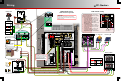
N
E
U
L1 L2
GRID
L1 L2
GEN
N
E
U
N
E
U
L1 L2
OUT
RELAY
AUX
+ -
12V
AUX
Switch
INV
Remote
Battery
Temp
GS8048A
1
8
9
ON/OFF
INV
8
22
3 7
19
21
19 19
5
6
17
10
11
12
13
14
15
16
20
20
18
FN-DC
Preferred screw
locations are
depicted here
16
NOTE:
The AC neutral bus bar is bonded to the
GSLC chassis. If the distribution panel
neutral is bonded to ground, remove the
bond from the neutral bus bar.
0.5" (1.3 cm)
Negative PV Cable Connections
Shunt
Bolt 3/8"
Lock
Washer
Flat
Washer
PV
Negative
(–)
DC
Negative (-)
Plate
(GS-SBUS)
22
20
FM80
Negative
(–)
Bolt 3/8"
Lock
Washer
Shunt
20
Battery
Positive (+)
Bolt 3/8"
Nut
Wallboard
5.0" (12.7 cm)
Wall Stud
Wall Stud
16"
(40.6 cm)
Wall
Bracket
Plywood (Optional)1
2