
Installation Guide

EN-Rev IM/GN-AM-EN/A13 Copyright © November, 2018. Canadian Solar Inc.
10
|
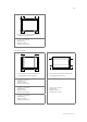
CS1K-MS, CS1H-MS
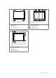
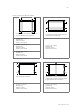
Use four clamps on the long side. Mounting rails
run perpendicularly to the long side frame.
A1 range = (0 – 239) mm
Maximum Load:
Uplift load ≤ 2000 Pa
Downforce load ≤ 2000 Pa
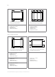
A1
A1 A1
A1
A1 range = (240 – 550) mm
Maximum Load:
Uplift load ≤ 2400 Pa
Downforce load ≤ 2400 Pa
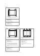
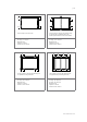
A1 range = (240 – 330) mm
Maximum Load:
Uplift load ≤ 2400 Pa
Downforce load ≤ 5400 Pa
Notice: when the modules need to be installed in
heavy snow area, please inform Canadian Solar Inc.’s
technical support department in writing for advices.
Failure to follow this notice may violate the warranty.
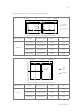
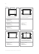
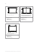
Use six clamps on the long side. Mounting rails
run perpendicularly to the long side frame.
A3 range = (80 –380) mm
A5 range = (80 –380) mm
Maximum Load:
Uplift load ≤ 2400 Pa
Downforce load ≤ 5400 Pa
Notice: This method is recommended for better
reliability.
A3
A3 A5
A5A4A4
A4A4