
Installation Guide


REC Installation Manual - REC Alpha Series - UL 6
Rev A . Ref: NE
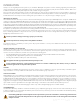
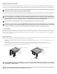
MOUNTING METHODS: CLAMPING WITH RAILS PARALLEL TO THE SHORT SIDE
REC Alpha solar panels secured by clamping to mounting rails has been found to comply with UL & UL requirements for downward pressure,e.g., snow,
of up to psf ( Pa or Pa design load*) and upward pressure,e.g., wind, of up to . psf ( Pa or Pa design load*) according to the instructions
below (*design loads apply a safety factor of . to the stated test load, e.g., test load Pa / . = Pa design load). Site-specific factors such as high winds
or snow levels must be taken into consideration to ensure this limit is not exceeded. These instructions must be followed for each clamping method used:
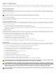
• Clamps must be positioned so that both the minimum grip length and the center point of each clamp are located in the required clamping zone,
• Follow the clamp manufacturer’s instructions to install the clamps, including the recommended applied torque,
• The distance between the end clamp and the end of the rail must be a minimum of in ( mm).
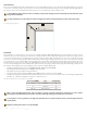
When clamping to a rail-based construction, the rails must run underneath the panel to provide support to the frame. Where the rails are positioned parallel to
the short side of the panel as per the examples shown in fig. , the clamping zones shown in fig. are to be followed. The positioning of the rails must ensure
that the minimum grip length of the clamp and the central point of the fixation, e.g., the bolt, is fully within the required clamping zone as indicated in fig. :
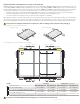
Each panel must be clamped in a minimum of four separate zones, with one clamping point in each quarter of the panel (fig. 3).
Fig. : Clamping of panels with rails parallel to the short side
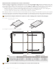
Fig. : Clamping zones for panels with rails parallel to short side (in [mm])
9.8 - 4 in
[250 - 100 mm]
4 - 9.8 in
[100 - 250 mm]
9.8 - 4 in
[250 - 100 mm]
4 - 9.8 in
[100 - 250 mm]
16.5-25.6 in
[420-520 mm]
8.2-13.4 in
[340-420 mm]
8.2-13.4 in
[208-340 mm]
0-8.2 in
[0-208 mm]
20.5-25.6 in
[520-650 mm]
25.6-20.5 in
[650-520 mm]
25.6-16.5 in
[520-420 mm]
13.4-8.2 in
[420-340 mm]
13.4-8.2 in
[340-208 mm]
8.2-0 in
[208-0 mm]
Scale: 1:1.57
GR
GR
GR
16.5-25.6 in
[420-520 mm]
8.2-13.4 in
[340-420 mm]
8.2-13.4 in
[208-340 mm]
0-8.2 in
[0-208 mm]
20.5-25.6 in
[520-650 mm]
25.6-20.5 in
[650-520 mm]
25.6-16.5 in
[520-420 mm]
13.4-8.2 in
[420-340 mm]
13.4-8.2 in
[340-208 mm]
8.2-0 in
[208-0 mm]
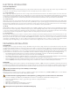
Rail positioning
Rail positioning
Legend: Test Load Design Load
(= Test load / 1.5)
Panel quarter division
Max. downward load Max. upward load Max. downward load Max. upward load
. . in - mm] psf Pa) . psf ( Pa) psf Pa) . psf ( Pa)
. . in, . - . in - mm; - mm] psf Pa) psf ( Pa) psf Pa) psf ( Pa)
. in, . - . in - mm; - mm] (long side)
psf ( Pa) psf ( Pa) psf ( Pa) psf ( Pa)
- . in [ - mm] (short side)
Not permied (in cases where only four () clamping points are used, additional clamps, i.e., ≥ may be freely located on panel frame)
If the panel is secured in two different colored clamping zones, it is rated to the lower load value only.
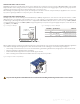
a) Long side mounting b) Short side mounting