
Installation Guide


9.
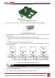
PushtheRS485terminalblockfirmlyallthewayintotheconnectorontherightsideofthe
communicationboard.
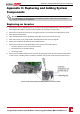
10.
TerminatethefirstandlastSolarEdgedeviceinthechainbyswitchingaterminationDIP-switchinside
theinvertertoON(movetheleftswitchup).Theswitchislocatedonthecommunicationboardand
ismarkedSW2.
Figure 32: RS485 termination switch
NOTE
Only the first and last SolarEdge devices in the chain should be terminated. The other inverters in
the chain should have the termination switch OFF (down position).
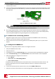
11. Ifnotusingsurgeprotection,connectthegroundingwiretothefirstinverterintheRS485chain;
makesurethegroundingwireisnotincontactwithotherwires.ForinverterswithaSafetySwitch,
connectthegroundingwiretothegroundingbus-barintheSafetySwitch.
To connect to the monitoring platform:
1. DesignateasingleinverterastheconnectionpointbetweentheRS485busandthemonitoring
platform.Thisinverterwillserveasthemasterinverter.
2. ConnectthemastertothemonitoringplatformviatheLANoption(referto)oranyoftheother
options.
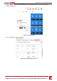
To configure the RS485 bus:
Allinvertersareconfiguredbydefaultasslaves.Toconfigurethemaster:
1. VerifytheON/OFF/PswitchisOFF.
2. VerifythatACison.
3. UseSetApptoaccesstheCommissioningmenuscreenasdescribedinCommunicationonpage35.
4.
FromtheCommissioningmenutapCommunication.TheCommunicationscreenisdisplayed.
5.
Selectthefollowingtoconfiguretheconnection:
l ServerèLAN
l RS485-1èProtocolè SolarEdge Master
l RS485-1èSlave Detect
Thesystemstartsautomaticdetectionoftheslaveinvertersconnectedtothemasterinverter.The
invertershouldreportthecorrectnumberofslaves.Ifitdoesnot,verifytheconnectionsand
terminations.
6. TochecktheslaveIDsandlastcommunicationtime,selectRS485-1èSlave List.
7. Verifytheconnectionofthemastertothemonitoringplatform,asdescribedinthenextsection.
-Single Phase Inverter with HD-Wave Technology Installation MAN-01-00541-1.0
52
Creating an RS485 Bus Connection