
Installation Guide

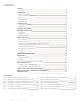

REC Installation Manual - REC Alpha Series - UL 6
Rev A . Ref: NE
PANEL INSTALLATION
REC solar panels are designed for capturing solar radiation and are not suitable for use as overhead or vertical glazing. The IP rating of the junction box
provides a level of protection that allows panels to be mounted in any orientation (see product technical specifications for exact rating). The panels are
considered to be in compliance with UL & UL , only when the panel is mounted according to the mounting instructions specified below:
Panels must be installed so that the cells are not shaded as this will drastically reduce electrical output. If partial shading is inevitable at
certain times of the day or year, it must be kept to an absolute minimum.
There are different options for securing REC solar panels depending on the design of the array. Ensure the mounting structure can withstand anticipated wind
and snow loads. Mounting hardware is not supplied by REC. Follow the mounting hardware manufacturer’s instructions and recommendations at all times.
Common hardware items such as nuts, bolts, star washers, lock washers and the like have not been evaluated for electrical conductivity or
for use as grounding devices and should be used only for maintaining mechanical connections and holding electrical grounding devices in
the proper position for electrical conductivity. Such devices, where supplied with the panel and evaluated through the requirements in UL
1703 & UL 61730, may be used for grounding connections in accordance with the instructions provided with the panel.
Remove any labels or stickers that may be on the front of the panels and ensure no residue is le on the glass.
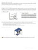
There must be a minimum clearance gap of 2.4 in (60 mm) between the uppermost part of the installation surface (e.g., rooop) and the
lowest part of the panel (i.e., underside of panel frame) to avoid any damage to the panel and to ensure sufficient airflow for cooling, helping
to improve performance. The surface below the panels must be kept clear of any objects that may cause damage to the panel.
RAIL SPECIFICATIONS
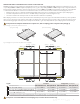
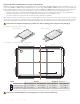
REC solar panels are typically installed on a rail-based mounting system. Rails must be suitable for the intended installation and able to withstand
anticipated snow and wind loads. When using mounting rails, ensure they run underneath the panel to provide support to the frame. The positioning of
the rail must ensure that the minimum clamp grip length and the central point of the fixation, e.g., the bolt, is fully within the required clamping zone as
indicated on the following pages.
CLAMP SPECIFICATIONS
REC panels have been evaluated to UL & UL standards for mounting using rails in combination with end and mid clamps Ensure the clamps
used are rigid and suitable for the planned installation and expected system design loads.
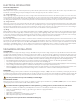
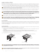
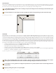
• Minimum grip length of . in ( mm); a grip depth of . . in - mm) (fig. ). The grip area must not extend onto the panel glass and/or cause
cell shading,
• Each panel must be clamped at a minimum of four points, in each quarter of the panel, as illustrated on the subsequent pages,
• Clamp installation must be carried out according to the manufacturer’s instructions, including specific hardware and torque requirements,
• Avoid the application of excessive pressure to prevent frame deformation.
Fig. : Clamp specifications: End and mid-clamps
In areas of snow build-up panels can be subjected to forces in excess of the stated limit even when snow depth does not appear extreme,
causing damage to the framework. If the installation is likely to be affected by this, further suitable panel support is recommended,
especially on the lower row of panels.
In the case of any questions regarding mounting systems, or if the mounting system to be used does not match any of the instructions
shown in this installation manual, please contact REC for further support.
Min. grip depth: . in ( mm)
Min. grip depth: . in ( mm)
Min. grip length:
. in ( mm)
Max. grip depth: . in ( mm)
Max. grip depth: . in ( mm)
Min. grip length:
. in ( mm)