
Product Specifications

© SolarEdge Technologies Ltd. All rights reserved. SOLAREDGE, the SolarEdge logo, OPTIMIZED BY SOLAREDGE are trademarks or registered trademarks of SolarEdge Technologies, Inc.
All other trademarks mentioned herein are trademarks of their respective owners. Date: 12/2018/V01/ENG NAM. Subject to change without notice.
(4)
For detailed ring sizing information refer to: http://www.solaredge.com/sites/default/les/ring_sizing_na.pdf
(5)
It is not allowed to mix P405/P505 with P320/P340/P370/P400 in one ring
(6)
A ring with more than 30 optimizers does not meet NEC rapid shutdown requirements; safety voltage will be above the 30V requirement
(7)
For SE14.4KUS/SE43.2KUS: It is allowed to inall up to 6,500W per ring when 3 rings are connected to the inverter (3 rings per unit for SE43.2KUS) and when
the maximum power dierence between the rings is up to 1,000W
(8)
For SE30KUS/SE33.3KUS/SE66.6KUS/SE100KUS: It is allowed to inall up to 15,000W per ring when 3 rings are connected to the inverter (3 rings per unit for SE66.6KUS/SE100KUS)
and when the maximum power dierence between the rings is up to 2,000W
Power Optimizer
For North America
P320 / P340 / P370 / P400 / P405 / P505
Optimizer model
(typical module
compatibility)
P320
(for 60-cell
modules)
P340
(for high-
power 60-cell
modules)
P370
(for higher-
power
60 and 72-cell
modules)
P400
(for 72 & 96-
cell
modules)
P405
(for thin lm
modules)
P505
(for higher
current
modules)
INPUT
Rated Input DC Power
(1)
320 340 370 400 405 505 W
Absolute Maximum Input
Voltage
(Voc at lowe temperature)
48 60 80 125
(2)
83
(2)
Vdc
MPPT Operating Range 8 - 48 8 - 60 8 - 80 12.5 - 105 12.5 - 83 Vdc
Maximum Short Circuit Current
(Isc)
11 10.1 14 Adc
Maximum DC Input Current 13.75 12.63 17.5 Adc
Maximum Eciency 99.5 %
Weighted Eciency 98.8 98.6 %
Overvoltage Category II
OUTPUT DURING OPERATION (POWER OPTIMIZER CONNECTED TO OPERATING SOLAREDGE INVERTER)
Maximum Output Current 15 Adc
Maximum Output Voltage 60 85 Vdc
OUTPUT DURING STANDBY (POWER OPTIMIZER DISCONNECTED FROM SOLAREDGE INVERTER OR SOLAREDGE
INVERTER OFF)
Safety Output Voltage per
Power Optimizer
1 ± 0.1 Vdc
STANDARD COMPLIANCE
EMC FCC Part15 Class B, IEC61000-6-2, IEC61000-6-3
Safety IEC62109-1 (class II safety), UL1741
RoHS Ye s
INSTALLATION SPECIFICATIONS
Maximum Allowed Syem
Voltage
1000 Vdc
Compatible inverters All SolarEdge Single Phase and Three Phase inverters
Dimensions (W x L x H) 129 x 153 x 27.5 / 5.1 x 6 x 1.1
129 x 153 x 33.5 /
5.1 x 6 x 1.3
129 x 159 x 49.5 /
5.1 x 6.3 x 1.9
129 x 162 x 59 /
5.1 x 6.4 x 2.3
mm / in
Weight (including cables) 630 / 1.4 750 / 1.7 845 / 1.9 1064 / 2.3 gr / lb
Input Connector MC4
(3)
Output Wire Type / Connector Double Insulated; MC4
Output Wire Length 0.95 / 3.0 1.2 / 3.9 m / ft
Input Wire Length 0.16 / 0.52 m / ft
Operating Temperature Range -40 - +85 / -40 - +185 ˚C / ˚F
Protection Rating IP68 / NEMA6P
Relative Humidity 0 - 100 %
(1)
Rated STC power of the module. Module of up to +5% power tolerance allowed
(2)
NEC 2017 requires max input voltage be not more than 80V
(3)
For other connector types please contact SolarEdge
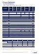
PV System Design Using
a SolarEdge Inverter
(4)(5)
Single Phase
HD-Wave
Single phase Three Phase 208V Three Phase 480V
Minimum String Length
(Power Optimizers)
P320, P340, P370,
P400
8 10 18
P405 / P505 6 8 14
Maximum String Length
(Power Optimizers)
25 25 50
(6)
Maximum Power per String
5700 (6000 with
SE7600-US - SE11400-
US)
5250 6000
(7)
12750
(8)
W
Parallel Strings of Dierent Lengths
or Orientations
Ye s