
Installation Guide
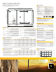
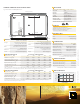


REC Installation Manual - REC Alpha Series - UL 6
Rev A . Ref: NE
ANNEX : INSTALLATIONS USING RAPID SHUTDOWN DEVICES
This section is applicable to all REC products referred to in this installation manual.
Rapid Shutdown (RSD) is the name given to the range of panel-level components that can be installed in PV system circuits installed on or in buildings
to reduce shock hazard for emergency responders. RSD devices can be supplied pre-installed by panel manufacturers or as a ‘retro-fit’ system made by
third-party manufacturers. From January , , Section . of the National Electrical Code (NEC) (in the U.S.A.) requires the panel-level
rapid shutdown of solar systems (replacing the previous array-level shutdown requirement of NEC ). This means that all conductors within an
array’s - ( mm) boundary have to be reduced to V or less within seconds of rapid shutdown initiation.
RSD devices may be used on REC solar panels where desirable or mandatory (note that the certification testing of solar panels does not include testing
with RSD devices). When installing an RSD device on an REC solar panel, follow the instructions provided by the device manufacturer and the instructions
specific for REC solar panels given below. Failure to follow the manufacturer and the REC instructions may invalidate the warranty.
INSTALLATION
i) Installation
• RSD devices are suitable for use wherever solar panels are suitable for installation. Observe any limitations set by the RSD manufacturer. (e.g.,
minimum mounting gap between RSD and rooop).
• When aaching an RSD device to a solar panel, it must be secured to the panel frame. Follow RSD manufacturer instructions to ensure optimum
mounting of RSD device and prevent any slippage during operation.
• RSD devices may also be aached to the mounting construction. In such cases, refer to the instructions provided by the manufacturer.
• Wherever possible, the installation of the RSD device should not cover the product label on the rear of the panel.
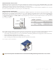
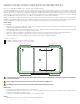
• RSD devices may only be installed on REC solar panels in the areas shown in the diagram below (fig. ):
Fig. : RSD device installation zones
Installation of RSD device in the green zone is permied.
Installation of RSD device in the red zone is not permied.
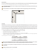
To avoid damage to the panel and to allow for thermal expansion, there must be a minimum gap of 0.1 in (2.5 mm) between the RSD device
and the panel backsheet.
The mounting holes in the panel frame must not be used for the installation of RSD devices.
The drilling of extra holes in the frame is not permied and will invalidate the panel warranty.
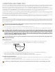
CONNECTION
• First ensure the installation of the RSD device is secure and safe.
• Following the device manufacturer’s instructions to connect the cables from the RSD device to the solar panel correctly (usually positive to
positive [+ to +] and negative to negative [- to -]).
• Connection to the next panel in the array should be done from the ‘free’ cables.
SAFETY
• Immediately disconnect the device if there is a problem during installation.
0 - 480 mm [0 - 18.9 in]
0 - 480 mm [0 - 18.9 in]
0 - 1016 mm [0 - 40 in]
0 - 480 mm [0 - 18.9 in]
0 - 480 mm [0 - 18.9 in]
0 - 1016mm [0 - 40 in]
GR
GR
GR