
Product Overview

www.white-rodgers.com
140a
HYDRONIC
HYDRONIC
CONTROLS
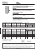
WELL IMMERSION SINGLE CONTROL
Types for use as High Limit, Reverse Action or SPDT Switching Ac-
tion: May Be Mounted Either Horizontal or Vertical.
FEATURES
• Extra capillary length for extended shank wells.
• Special screw terminals with “ears” securely hold solid and stranded wires.
• Screwdriver-adjustable differential with direct-read indicator.
• Knockouts on top and bottom and plenty of wiring room.
• Hydraulic action element — fast acting.
SPECIFICATIONS
Dimensions. . . . . . . . . . . . . . . . . . . . . . . . 5
3
/
8
”H + 2
5
/
16
” coil x 2
9
/
16
”D
Finish . . . . . . . . . . . . . . . . . . . . . . . . . . . . Grey
Agency . . . . . . . . . . . . . . . . . . . . . . . . . . . U.L. listed
Full Motor Rating Valves and
Model Switch Electrical (Full Load) Relays
Number Range Differential Action Rating 120 VAC 240 VAC 24 VAC 0.3-12v DC
11D18-1 ➀ 100 to 240°F 5 to 45°F Open on Rise HTV 10.0A 6.0A 6.0A 1.0A
(38 to 116°C) (3 to 25°C) See page 416
11D31-1 100 to 240°F 7 to 45°F SPDT HH 7.4A 3.7A 2.9A —
(38 to 116°C) (4 to 25°C) See page 416
➀ Has U.L. approved adjustable dial stop, factory set at 150°F maximum.
11D18-1
PARTS AND ACCESSORIES See end of this section for additional parts and accessories
• F145-0163 — Tube heat conductive compound
• F145-0650 — Well adapter and heat conductive compound
• F71-0924 — Well adapter only
• Immersion wells — see page 147
TYPES WITH BULBS DIRECTLY INTERCHANGEABLE WITH HONEYWELL (3
9
/
16
” x
3
/
8
”) No wells included.
SPDT Contact Structure
HH Rated Controls
Switch Action
R-B Open on Rise
R-W Close on Rise
Full Motor Rating Valves and
Model Switch Electrical (Full Load) Relays
Number Range Differential Action Rating 120 VAC 240 VAC 24 VAC 0.3-12v DC
1131-102 ➀ 100 to 240°F 7 to 45°F SPDT HH 7.4A 3.7A 2.9A —
(38 to 116°C) (4 to 25°C) See page 416
11B05-101 100 to 240°F 5 to 45°F Close on Rise HT 14.0A 7.0A — —
(38 to 116°C) (3 to 25°C) See page 416
11B18-101 ➀ 100 to 240°F 5 to 45°F Open on Rise HTV 10.0A 6.0A 6.0A 1.0A
(38 to 116°C) (3 to 25°C) See page 416
11B18-153 ➁ 35 to 110°F Fixed 2°F Open on Rise HTV 10.0A 6.0A 6.0A 1.0A
(2 to 43°C) (1°C) See page 416
11B27-9 ➂ 100 to 500°F Manual Open on Rise FG 14.0A 7.0A 5.6A —
(40 to 260°C) Reset See page 416
11B27-10 ➂ 250 to 650°F Manual Open on Rise FG 14.0A 7.0A 5.6A —
(121 to 343°C) Reset See page 416
11B30-104 ➃ 100 to 240°F 8 to 45°F Open on Rise HTV 10.0A 6.0A 6.0A 1.0A
(38 to 116°C) (4.5 to 25°C) See page 416
➀ Has U.L. approved adjustable dial stop, factory set at 150°F maximum.
➁ Has special straight well for 4” x
7
/
16
” straight bulb.
➂ Has 7’ capillary and 3” x
5
/
16
” straight bulb.
➃
3
/
4
” standard shank well.
TYPES WITH TAPERED BULBS (2
7
/
16
” x
7
/
16
”) All types include
1
/
2
” standard shank well, unless otherwise specified.
CONTRACTOR TIP: TESTING AUTOMATIC TEMPERATURE CONTROLS To verify a control is opening and closing properly, disconnect
all power before testing. Testing must be performed with the sensing element at a temperature within the setting range of the control. For
most hydronic controls with a range of 100 to 240°F, a pan of hot water is sufcient to reach the control range.
Attach an ohmmeter or continuity tester across the Open on Rise contacts. Lower the temperature setting dial to the lowest setting.
If the lowest setting is below the temperature of the sensing element minus the differential of the control, the contacts should be open.
Raise the temperature dial slowly. When the setting is raised above the temperature of the sensor, the contacts should close.
Indicates Canadian Model Number: call 1-800-305-6953 to order