
Installation manual

INSTALLATION
EN / M-SC3.5 / May 2010 13
Insert a MasterBus terminating device into the
other communication port.
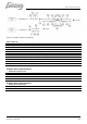
3 The Masterview Easy can be flush mounted or
panel mounted on a wall or board:
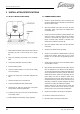
Figure 17
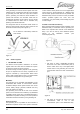
o Flush mounting (see figure 17):
• Remove the outer housing and remove the
front from the panel.
• Make a cut out in the mounting wall and drill
the holes using the saw template in the box
or using the dimensions at the back of the
front plate.
• Mount the MasterView Easy onto the panel
(1) and then reattach the front (2).
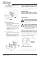
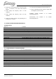
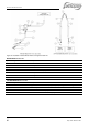
o Panel mounting (see figure 18):
• Remove the outer housing and remove the
front.
• Drill the holes using the dimensions at the
back of the front plate and fasten the outer
housing (1).
• Click the panel into the outer housing (2).
• Reattach the front (3).
Figure 18
During first commissioning the generator set will be
recognized by the MasterBus network automatically. This
may take a few seconds. Then the Masterview Easy will
show the initial screen.
Refer to the operation manual of the MasterView Easy for
initial settings and operating instructions.
Event based commands
One of the main features of MasterBus is the possibility of
programming for interactive operation of the connected
devices, including automatic starting and stopping of the
generator set. This is done by means of event based
commands. Refer to the operation manual of the
MasterView Easy for details about programming these
event based commands.
Whisper Power cannot be held responsible
for damage caused by unattended running
of the generator due to the use of event
based commands.
Using event based commands the
generator can start unexpectedly. When
working on the electrical system, the 30
Amp fuse must be removed from the Local
Control Panel and the battery plus cable
must be removed from the battery.
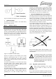
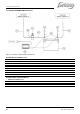
Connection of an emergency stop / fire alarm switch
To connect an emergency stop button or to stop the
generator automatically in case of a fire alarm, you can
use the bypass connection between wires 13 and 14 that
come from the The Digital Diesel Control Panel. See fig.
19. To do so, remove the top cover plate of the
connection box to get access to the wiring loom.
Figure 19: Location of the connection box
Disconnect the bypass between wires 13 and 14 and then
replace it by an emergency switch or a potential free fire
alarm switch with normally closed contacts (figure 20).