INSTALLATION MANUAL M-SC3.5 - 3000 RPM - Marine diesel generating set 230V / 50Hz Digital Diesel Control Art.nr. 40261141 WHISPER POWER BV Kelvinlaan 82 9207 JB Drachten Netherlands Tel.: +31-512-571550 Fax.: +31-512-571599 www.whisperpower.eu V1.
CONTENTS CONTENTS: 1 INSTALLATION ............................................................................................................................................................... 3 1.1 Location .............................................................................................................................................................. 3 1.2 Instructions for optimal sound and vibration insulation ............................... Fout! Bladwijzer niet gedefinieerd.
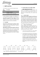
INSTALLATION 1 INSTALLATION This installation manual is valid for the following models: 1.2 INSTRUCTIONS FOR OPTIMAL SOUND Part number Position the generating set as low as possible in the vessel. As the generating set is already secured to the base frame by means of flexible engine mountings, the frame can be mounted directly to the vessel’s main structure. AND VIBRATION INSULATION Description M-SC3.5 / 230V 3000rpm wet exhaust MasterBus controlled M-SC3.
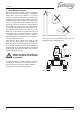
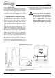
INSTALLATION 3 Never connect the base of the generating set directly to bulkheads or tanks. 1.3 VENTILATION The generating set normally draws air from the engine room. Engine rooms with natural ventilation must have vent openings of adequate size and location to enable the generating set to operate without overheating. To allow an ample supply of air within the temperature limits of the generating set an opening of at least 100 cm2 is required.
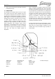
INSTALLATION 1.4 CONNECTIONS The generating set comes supplied with all supply lines and output cable (i.e. electric cables, cooling water connections, exhaust, fuel lines etc.) already connected to the engine and generator. The supply lines are fed through the capsule’s front base. The connections are marked as shown in figure 2. All electrical connections, cable types and sizes must comply with the appropriate national regulations. Supplied cables are rated for ambient temperatures up to 70°C.
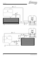
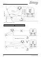
INSTALLATION 1 Fuel return; 2 Fuel supply; 3 Prefilter / water separator (optional); 5 Fuel tank; 6 Standard fuel lift pump; 7 Standard fuel filter. Figure 3: Fuel supply (fuel tank is above the generating set) 1 Fuel return; 2 Fuel supply; 3 Prefilter / water separator (optional); 4 Extra fuel lift pump (optional); 5 Fuel tank; 6 Standard fuel lift pump; 7 Standard fuel filter. Figure. 4: Fuel supply (fuel tank is above the generating set) 6 May 2010 / M-SC3.
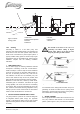
INSTALLATION min. 60 cm max. 120 cm Figure 5: Internal cooling system 1.4.2 1 Water level 2 Water/exhaust separator 3 Seacock 4 Waterlock 5 Air vent; 6 Water strainer; 7 Seacock. Cooling This should not be done in the case of a generating set! When sailing at higher speeds, water will be forced into the inlet and your generating set will overflow! Intercooling is based on a raw water pump, heat exchanger and water-injected exhaust.
INSTALLATION 4 SIPHON BREAKER (AIR VENT) When the point of water injection is below the waterline, then -when the engine is stopped -there is a risk that the cooling water may enter the engine as a result of siphoning. To avoid this happening, the generating set is designed to accommodate a siphon breaker (air vent). In the standard delivery the connections are bypassed. Hose of 12.5 mm (1/2") inner diameter should be used.
INSTALLATION 1.4.3 Exhaust system Water is injected in the exhaust system of the generating set. In this way the cooling water that has passed the heat exchanger is mixed with the exhaust gases. Temperature and volume of the gases are thereby reduced considerably, so that a rubber exhaust hose can be used and the level of noise is reduced as well. 1 situated preferable along the ship’s keel center line. It is recommended to install an extra muffler (see figure 9, ref.
INSTALLATION Figure 10: Super silent exhaust system 1 Water level; 2 Water/exhaust separator; 3 Seacock; 4 Waterlock; Max. length A – B = 2.5 m. (8 ft.) Figure 11: Only after the exhaust / water separator the exhaust hose may have a length up to 7,5m. 10 May 2010 / M-SC3.
INSTALLATION 2 "SUPER SILENT" EXHAUST SYSTEM See figure 10. In order to reduce the noise level of the generating set to a minimum, an option to reduce the exhaust noise further (especially exhaust water splashing) is an exhaust/water separator. The exhaust/water separator allows the cooling water to be ejected through a line separate from the exhaust fumes and also functions as a goose neck to prevent water from flooding the engine.
INSTALLATION If the generating set and the exhaust system have been installed correctly, neighbouring boats will not be disturbed by generating set noise, With the "super silent" exhaust system, generating set noises are almost inaudible. For optimal noise reduction, the sea water outlet from the exhaust/water separator (center outlet on the unit) should be installed below the water level to eliminate noisy splashing of the effluent sea water.
INSTALLATION Insert a MasterBus terminating device into the other communication port. 3 The Masterview Easy can be flush mounted or panel mounted on a wall or board: During first commissioning the generator set will be recognized by the MasterBus network automatically. This may take a few seconds. Then the Masterview Easy will show the initial screen. Refer to the operation manual of the MasterView Easy for initial settings and operating instructions.
INSTALLATION included in the standard supply. A high efficiency battery charging unit can be ordered from Mastervolt which is able to charge both the ship’s main battery and the starter battery. Also a small charger can be used to charge the starter battery only, such as the IVO SMART 12/10. Fig. 20: Connection for emergency stop / fire alarm switch 2 STARTER BATTERY For starting, the Whisper requires a 12V starter battery with the following capacity: Model Minimum capacity M-SC3.
INSTALLATION authorities. All electrical safety/shutdown and circuit breaking systems have to be installed onboard as the generating set itself cannot be equipped with such equipment for every possible variation. The vessel’s power supply system should be suitable and safe for the AC voltage which is applied and the power that will be generated. Special attention has to be paid on dividing the system in branches which are fused individually.
INSTALLATION SPECIFICATIONS 2 INSTALLATION SPECIFICATIONS 2.1 M-SC3.5 INSTALLATION TABLE Figure 23 1 Install a steel foundation plate between ship’s hull and generating set, with 4 shock mounts (ref. to figure. 23). 2 Mount the generating set directly to the foundation plate. 3 Connect the (sea) water inlet to the strainer. 4 Connect exhaust system. 5 Connect a siphon breaker or ‘air vent’ into the cooling circuit, if necessary. 6 Connect ‘fuel supply line’ to the water separator/ fuel filter.
INSTALLATION SPECIFICATIONS 12 Check when the generating set is running, the delay of 3 – 10 seconds in the power source selector transfer. 13 Check voltage and frequency under ‘no load’ conditions. 14 Check voltage and frequency under ‘full load’ conditions. 15 Check if the battery charger of the generating set is working (max. 14.5 Volt). 16 Close the sound shield and check the noise level. 17 Stop the generating set and check the engine again for leakages of oil, fuel or water.
INSTALLATION SPECIFICATIONS 2.5 INSTALLATION MATERIALS M-SC3.5 Figure 24: Installation materials battery installation kit BATTERY INSTALLATION KIT 55 Ah pos.
INSTALLATION SPECIFICATIONS Figure 25: Installation materials fuel supply kit FUEL SUPPLY KIT pos.
INSTALLATION SPECIFICATIONS Figure 26: Installation materials Water inlet kit and Syphon breaker kit WATER INLET KIT 12.5 mm pos. qty article no 1 1 50230052 2 1 50230042 3 3 50221016 4 3 50221521 5 3m 50220055 6 1 50230062 7 1 50230067 TOTAL 50230201 description Intake strainer 3/4" Lever operated ball valve FF 3/4" Male hose connection 3/4"x13 Hose clamp stainless 12-20 Cool. water hose transp.
INSTALLATION SPECIFICATIONS Figure 27: Installation materials “Delta” exhaust kit ø 40 mm (1 5/8”) and water separator kit 40 mm (1 5/8”) “DELTA” EXHAUST KIT Ø 40 mm (1 5/8”) pos. qty article no description 22 8 50221504 Hose clamp stainless 32-44 mm 23 3m 50220033 Marine exhaust hose 40 mm (1⅝”) 24 1 50230093 Waterlock 40 mm Delta 25 1 50230038 Brass hull fitting hose connection 1¼"x40 TOTAL 50230251 DELTA EXHAUST KIT 40 mm “DELTA” WATERSCHEIDER KIT 40 mm (1 5/8”) pos.
INSTALLATION SPECIFICATIONS Figure 28: installation materials base plate kit BASE PLATE KIT for M-SC3.5 (3000 rpm) pos. 61 62 63 64 65 66 67 TOTAL 22 qty 4 1 4 4 4 4 4 article no 50230552 50230012 50211449 50211251 50211438 50211447 50211241 50230207 description Rubber mounting up to 70 kg RAB3 HD base plate 3500 yellow zinc plated Washer spring SP M12 Bolt hexagonal socket ZP M12x40 Washer SP M10x30x1,5 Washer spring SP M10 Bolt hexagonal socket ZP M10x25 BASE PLATE KIT M-SC3.5 May 2010 / M-SC3.
DIAGRAMS & DRAWINGS 3 DIAGRAMS & DRAWINGS 3.1 DC WIRING DIAGRAM Figure 29a: DC wiring M-SC3.5 grounded (part. Nr. 51200500) EN / M-SC3.
DIAGRAMS & DRAWINGS Figure 29b: DC wiring M-SC3.5 ungrounded (part. Nr. 51200506) 24 May 2010 / M-SC3.
DIAGRAMS & DRAWINGS 3.2 WIRING NAMES AND COLOURS Wire name Battery + Battery Glow + Start solenoid + Stop solenoid Stop solenoid + Fuel valve + Fuel valve Fuel pump + Fuel pump Charger a Charger b Safety switch + Safety switch Battery + Battery + Wire number 1 2 3 4 5* 6 7 8 9 10 11 12 13 14 15* 16* Colour White White White White White White White White Brown Black White White White White White White Cross section 2.5 mm2 2.5 mm2 2.5 mm2 2.5 mm2 2.5 mm2 1.5 mm2 1.5 mm2 1.5 mm2 1.5 mm2 1.
DIAGRAMS & DRAWINGS 3.3 AC WIRING DIAGRAM 230V / 50HZ EARTH AND NEUTRAL NOT CONNECTED 230V 50Hz EARTH AND NEUTRAL CONNECTED 230V 50Hz Figure 30 AC wiring diagram 26 May 2010 / M-SC3.
DIAGRAMS & DRAWINGS 3.4 DIMENSIONS MASTERVIEW EASY PANEL Figure 31: Dimensions of the panel without and with outer casing. All dimensions are in mm (inch) 3.5 DIMENSIONS M-SC3.5 Top view Aufsicht Box dimensions: Kastenabmessungen: L nge : 505 mm • width: 505 mm [19.9 inch] Breite : 400 mm • depth: 400 mm [15.7 inch] H he : 500 mm • height: 500 mm [19.
MASTERBUS 4 MASTERBUS monitoring, control and configuration of all connected MasterBus equipment. 4.1 WHAT IS MASTERBUS? All devices that are suitable for MasterBus are marked by the MasterBus symbol. MasterBus is a fully decentralized data network for communication between the different Mastervolt system devices. It is a CAN-bus based communication network which has proven itself as a reliable bus-system in automotive applications.
MASTERBUS 4.3 HOW TO SET UP A MASTERBUS NETWORK Each device that is suitable for the MasterBus network is equipped with two data ports. When two or more devices are connected to each other through these ports, they form a local data network, called the MasterBus. Keep the following rules in mind: The electric power for the network comes from the connected devices. At least one device in the network should have powering capabilities (see specifications).
NOTES NOTES 30 May 2010 / M-SC3.
Kelvinlaan 82, 9207 JB Drachten, Netherlands Tel : + 31-512-571550 / Fax : + 31-512-571599 www.whisperpower.eu / info@whisperpower.