
Product Manual

Page 1
9
5
1
6
2
7
3
8
4
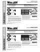
Mounting Surface
Thickness
.0625” (1/16”)
.125” (1/8”)
.1875” (3/16”)
.25” (1/4”)
.375” (3/8”)
Mounting Hole
Diameter
4.47”
4.50”
4.50”
4.53”
4.56”
GROMMET MOUNTING / HOLE CHART
W
H
E
L
E
N
M
O
D
E
L
2
G
S
E
R
I
E
S
W
H
E
L
E
N
M
O
D
E
L
2
G
S
E
R
I
E
S
WARNING!
As mounting this product requires drilling
holes, the installer MUST be sure that no
vehicle components or other vital parts could
be damaged by the drilling process. Check
both sides of the mounting surface before
drilling begins. Also de-burr any holes and
remove any metal shards or remnants. Install
grommets into all wire passage holes.
See reverse for Scan-Lock™ procedures and flash patterns
SPECIFICATIONS (12V)
12.8VDC ± 20%
0.5A
0.3A
VOLTAGE -
CURRENT (PEAK) -
CURRENT (AVG.) -
SPECIFICATIONS (24V)
25.6VDC ± 20%
0.30A
0.120A
VOLTAGE -
CURRENT (PEAK) -
CURRENT (AVG.) -
WHT/VIO - Scan-Lock™
BLK - Ground
YEL (or RED) - +12VDC
WHT/VIO - Scan-Lock™
BLK/WHT - Ground
YEL (or RED) - +24VDC
2G
Warning
Light
(12V)
2G
Warning
Light
(24V)
9
5
1
6
2
7
3
8
4
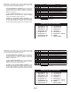
Mounting Surface
Thickness
.0625” (1/16”)
.125” (1/8”)
.1875” (3/16”)
.25” (1/4”)
.375” (3/8”)
Mounting Hole
Diameter
4.47”
4.50”
4.50”
4.53”
4.56”
GROMMET MOUNTING / HOLE CHART
W
H
E
L
E
N
M
O
D
E
L
2
G
S
E
R
I
E
S
W
H
E
L
E
N
M
O
D
E
L
2
G
S
E
R
I
E
S
WARNING!
As mounting this product requires drilling
holes, the installer MUST be sure that no
vehicle components or other vital parts could
be damaged by the drilling process. Check
both sides of the mounting surface before
drilling begins. Also de-burr any holes and
remove any metal shards or remnants. Install
grommets into all wire passage holes.
See reverse for Scan-Lock™ procedures and flash patterns
SPECIFICATIONS (12V)
12.8VDC ± 20%
0.5A
0.3A
VOLTAGE -
CURRENT (PEAK) -
CURRENT (AVG.) -
SPECIFICATIONS (24V)
25.6VDC ± 20%
0.30A
0.120A
VOLTAGE -
CURRENT (PEAK) -
CURRENT (AVG.) -
WHT/VIO - Scan-Lock™
BLK - Ground
YEL (or RED) - +12VDC
WHT/VIO - Scan-Lock™
BLK/WHT - Ground
YEL (or RED) - +24VDC
2G
Warning
Light
(12V)
2G
Warning
Light
(24V)
©2005 Whelen Engineering Company Inc.
Form No.13998A (062207)
Route 145, Winthrop Road,
Chester, Connecticut 06412
Phone: (860) 526-9504
Fax: (860) 526-4078
Automotive: Lightheads
Installation Guide:
2G-series Warning Lighthead
®
ENGINEERING COMPANY INC.
Internet: www.whelen.com
Sales e-mail: autosale@whelen.com
Canadian Sales e-mail: autocan@whelen.com
Customer Service e-mail: custserv@whelen.com
Installation:
1. Using the chart provided, cut an appropriately sized hole
(based on the thickness of the mounting surface).
2. Install the rubber grommet into the vehicle, then snap the
lighthead into the rubber grommet. Extend the wires to your
power source and switch(s). All customer supplied wires
that connect to the positive terminal of the battery, must
be sized to supply at least 125% of the maximum
operating current and be fused at the battery to carry
the load.
3. Wire the lighthead using the wiring diagrams shown above.