
Specifications


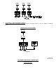
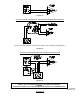

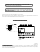


FIGURE 10.
(Front panel controls, switches and indicators.)
NOTE:
ALL CONTROLS ROTATE CLOCKWISE TO INCREASE AND
COUNTERCLOCKWISE TO DECREASE.
EXTERNAL CONTROLS AND INDICATORS (FIGURE 10)
:
POWER ON-OFF SWITCH (ILLUMINATED)
:
The light inside the switch will illuminate when the AC cord is plugged into a 120 VAC source and the power switch is
pressed to the ON position. (Set at factory in OFF position.)
MASTER VOLUME CONTROL
:
Adjusts the total output level of the amplifier without disturbing the individual settings of the microphone, telephone and
auxiliary input volume controls. (Set at factory in minimum position.)
TEL/MIC 1 INPUT VOLUME CONTROL
:
Adjusts the volume of either the TEL (Telephone) paging or MIC 1 input. (Set at factory in the minimum position.)
AUX 1/AUX 2 INPUT VOLUME CONTROL
:
Adjusts the volume of the AUX 1/AUX 2 inputs. (Set at factory in the minimum position.)
BASS AND TREBLE CONTROLS
:
Adjusts bass and treble for optimum tonal balance of the output signal. The amplifier frequency response is flat with the
knob indicators pointing straight up (Dot #6). (Set at factory in Dot #6 position.)
TEL/MIC 1 SELECTOR SWITCH
:
Switch to TEL position for telephone paging, or switch to MIC 1 position when using a microphone. (Set at factory in the
TEL position.)
AUX 1/AUX 2 SELECTOR SWITCH
:
Switch to either AUX 1 or AUX 2 position, depending upon which of 2 program source inputs are utilized. (Set at factory
in AUX 1 position.)
HORN PROTECT/LO-CUT SWITCH
:
This switch is located on the lower right hand side of the rear panel. Turn the switch ON whenever horns are used in the
system. This will protect the horn voice coils from damage by filtering out low frequencies inherent in some types of
music when played at high power settings. (Set at factory in OFF position.)
PEAK LEVEL INDICATOR
:
Occassional flickering of the LED indicates momentary peak levels, and is a normal operating condition. Steady
illumination of the LED is an indication that an overdrive (clipping) condition may exist. If distortion is audible, then lower
the appropriate input volume control, and/or the master volume control.
P82423 C
Sheet 8 of 10
INTERNAL SWITCHES (FIGURE 11)
:
There are two internal switches. These are ALC (limiter) ON-OFF, and MUTE ON-OFF switches. They are accessed by
removing the amplifier cover.