
Specifications


paging access, see Figures 9A, B & C. For Tip and Ring connections to Wheelock Zone Controls, refer to the specific
zone control installation instructions.
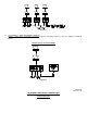
MICROPHONE INPUTS (FIGURE 3)
: Connect balanced low-impedance microphone wires to the input screw terminals
marked LO-Z. The shield must be connected to the GND screw terminals. An unbalanced microphone may be
connected to the same screw terminals. However, one of the two LO-Z terminals for that input must be connected to the
adjacent screw terminal marked GND. Install a jumper wire, between one LO-Z screw terminal and the GND screw
terminal.
NOTE:
TO AVOID POSSIBLE INTERFERENCE, THE MICROPHONE INPUT CABLE
SHOULD BE A SHIELDED CABLE, WITH THE SHIELD CONNECTED TO THE
INPUT
GND TERMINAL.
MIC 2 is a low impedance (LO-Z) microphone input channel. TEL/MIC 1 is a switch selectable telephone paging, or low
impedance (LO-Z) microphone input channel.
INPUT CONNECTIONS
FIGURE 3.
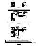
AUXILIARY INPUTS (FIGURE 4)
:
To connect an FM tuner, CD player, tape player, tone generator, or any other line level program source (i.e., mic/line
mixer) to either the AUX 1 or AUX 2 input jacks on the back panel, use a single conductor shielded cable terminated in a
standard RCA type phono plug.
AUX 1/AUX 2 is a high impedance (HI-Z) input channel providing a selection of 2 separate inputs.
AUX 1/AUX 2
HIGH IMPEDANCE (HI-Z) INPUTS
FIGURE 4.
P82423 C
Sheet 4 of 10
OUTPUT CONNECTIONS (FIGURES 5&6)
REFERRING TO FIGURE 5
:
Connect 2 output wires from the speaker load, to the COM screw terminal and the selected constant voltage terminal, (i.e.
25V or 70V). The constant voltage distribution method facilitates the use of multiple speakers in parallel with a single
amplifier. Note that each speaker must have its own 25V or 70V line-matching transformer. Select the wattage tap on the
line matching transformer of each speaker, for the power (volume) desired.